
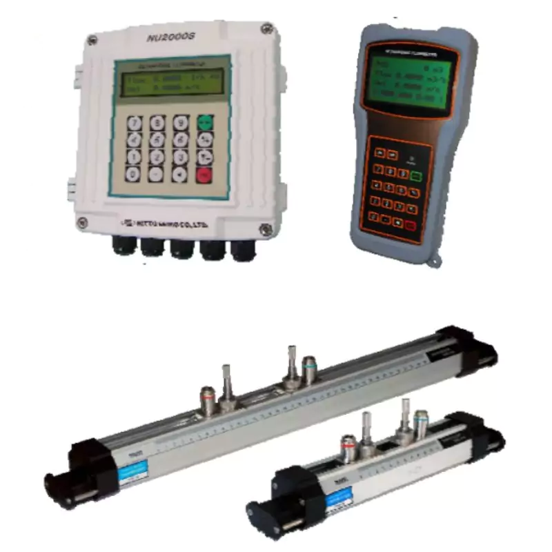
Nitto Seiko Ultrasonic Flow Meter
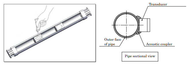
This is an ultrasonic flow meter of the clamp-on variety that can gauge liquid flow outside of a conduit.
This flow metre uses the propagation time difference method, whose ultrasonic propagation time differs depending on the rate of liquid flow in a pipe.
Due to the ability to measure from outside of a pipe, it is possible to measure various types of liquid without worrying about corrosion.
We have hand-held types that are appropriate for examining and inspecting the flow of various places in addition to wall-mount types that are stable for permanent standing.
-
 Original Products
 -
 Warranty Against Defects
 -
 Returns & Refunds Policy
 -
 Ships Worldwide
 -
 Dedicate Support

- Features
- Specification
- Measurement principle
- Characteristic of accuracy
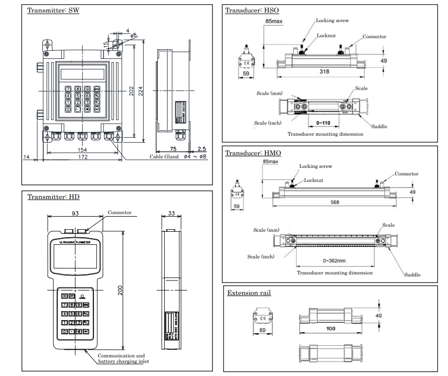
- External dimension
- Caution for installation
- Model and specification code
- It is available for installing to the current pipe-line.
- This can show installation
- This is completely non-wetted type, and it does not influence from pressure and conductivity of measured
- It is available for applying to small size piping by changing
- This is easy operation with large ten-key
- Small size and light weight hand held type makes convenience to
- Hand held type has chargeable battery of which 10 hours
For transducer
|
Article |
Contents |
|
Measured liquid |
Homogeneity liquid of which ultrasonic can propagate. (Water, Sea water, Industrial water, Acid, Alkali, Alcohol, etc) |
|
Turbidity |
10,000ppm or less |
|
LiquidTemp. |
-30~+90℃ (Same as ambient Temp. of transducer) |
|
Nominal size |
15~600mm (HS0:15~100mm, HM0:50~600mm) |
|
Material of pipe and lining |
Pipe shall be penetrated material by ultrasonic such as Copper, Stainless, PVC, Ductile iron. Lining must adhere to original pipe. (Lining material: Tar-epoxy, Mortar, Rubber, etc.) |
|
Flow rate range |
0~±10m/s |
|
Nos. of traverse line |
1 line |
|
Method |
Propagation time difference by ultrasonic pulse |
|
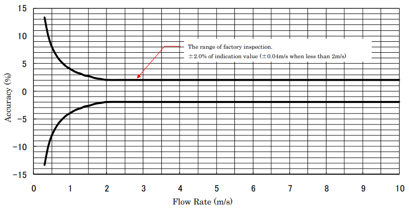
Accuracy (Calibrated accuracy at factory) |
±2.0% of indicated value (In case of less than 2m/s of flow rate, accuracy is ±0.04m/s) Note) It is required the pipe filled with liquid, and ideal velocity distribution. Note) It is required longer straight pipe than specified. |
|
Protection level |
IP67 |
|
Length of code |
5m as standard. (Please inquiry in case more length is required) |
For transmitter
|
|
Article |
Contents |
|
||
|
Component |
Wall mount type |
Hand held type |
|||
|
Power |
For AC: 100~220V AC±10% 50/60Hz For DC: 24V DC±10% |
100~220V AC±10% 50/60Hz 10 Hrs operation is available at full charge. |
|||
|
Power consumption |
1.5W or less |
2W or less |
|||
|
Ambient Temp. |
-10~+60℃ (Humidity 85% or less) |
||||
|
Atomosphere |
Avoid direct sunshine, radiant heat, corrosive environment, and explosive atomosphere |
||||
|
Analog output |
Kind of signal |
4~20mADC |
|
||
|
Converted Precision |
0.1% |
||||
|
Arrowable load resistance |
750Ω以下 |
||||
|
Open collector output |
Setting frequency |
1~9,999Hz |
|||
|
Current-V oltage |
DC80V、100mA or less |
||||
|
Voltage at ON |
1V or less |
||||
|
Relay output |
"Without", "Excessive flow", "Back flow alarm" etc. |
||||
|
Communication |
RS485 serial port |
RS232C serial port |
|||
|
Indication |
LCD (20 digits × 2 line), back light Momentary flow rate, integrated flow volume, etc |
LCD (16 digits × 4 line), back light Momentary flow rate, integrated flow volume, etc |
|||
|
Protection level |
IP65 |
|
|||
TR1:Transducer at upper stream TR2:Transducer at down stream θ :Incidence angle of sensor
V :Flow speed in a pipe
V1 :Ultrasonic propagation speed (Upper stream to downstream)
V2 :Ultrasonic propagation speed (Downstream to upper stream)
C :Sonic speed in a liquid
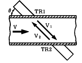
When install ultrasonic generator as above picture, ultrasonic from up-stream to down-stream is faster propagation than
its of down-stream to up-stream. This time difference is direct proportion to flow rate. Volumetric flow rate is calculated
by cross sectional area of pipe.
(Note) This is calibrated by manufacture’s factory inspection facility before delivery.
Please use calibration function if you find instrumental error due to operating environment.
Note) Pipe line shall be filled by liquid, and flow rate shall be ideal distribution.
Flow rate conversion table
Piping example/ Material: SGP Liquid: Water Value: Unit m3/H
|
Nominal Size |
Internal diameter |
Flow Rate (m/s) |
|||||||||
|
A |
mm |
1 |
2 |
3 |
4 |
5 |
6 |
7 |
8 |
9 |
10 |
|
15 |
16.1 |
0.7 |
1.5 |
2.2 |
2.9 |
3.7 |
4.4 |
5.1 |
5.9 |
6.6 |
7.3 |
|
20 |
21.6 |
1.3 |
2.6 |
4.0 |
5.3 |
6.6 |
7.9 |
9.2 |
10.6 |
11.9 |
13.2 |
|
25 |
27.6 |
2.2 |
4.3 |
6.5 |
8.6 |
10.8 |
12.9 |
15.1 |
17.2 |
19.4 |
21.5 |
|
32 |
35.7 |
3.6 |
7.2 |
10.8 |
14.4 |
18.0 |
21.6 |
25.2 |
28.8 |
32.4 |
36.0 |
|
40 |
41.6 |
4.9 |
9.8 |
14.7 |
19.6 |
24.5 |
29.4 |
34.3 |
39.1 |
44.0 |
48.9 |
|
50 |
52.9 |
7.9 |
15.8 |
23.7 |
31.6 |
39.6 |
47.5 |
55.4 |
63.3 |
71.2 |
79.1 |
|
65 |
67.9 |
13.0 |
26.1 |
39.1 |
52.1 |
65.2 |
78.2 |
91.2 |
104.3 |
117.3 |
130.4 |
|
80 |
80.7 |
18.4 |
36.8 |
55.2 |
73.7 |
92.1 |
110.5 |
128.9 |
147.3 |
165.7 |
184.1 |
|
100 |
105.3 |
31.4 |
62.7 |
94.1 |
125.4 |
156.8 |
188.1 |
219.5 |
250.8 |
282.2 |
313.5 |
|
125 |
130.8 |
48.4 |
96.7 |
145.1 |
193.5 |
241.9 |
290.2 |
338.6 |
387.0 |
435.4 |
483.7 |
|
150 |
155.2 |
68.1 |
136.2 |
204.3 |
272.4 |
340.5 |
408.6 |
476.7 |
544.8 |
612.9 |
681.0 |
|
200 |
204.7 |
118.5 |
237.0 |
355.4 |
473.9 |
592.4 |
710.9 |
829.3 |
947.8 |
1066.3 |
1184.8 |
|
250 |
254.2 |
182.7 |
365.4 |
548.1 |
730.8 |
913.5 |
1096.2 |
1278.9 |
1461.6 |
1644.3 |
1827.0 |
|
300 |
304.7 |
262.5 |
525.0 |
787.5 |
1050.0 |
1312.5 |
1575.0 |
1837.5 |
2100.0 |
2362.5 |
2625.0 |
|
350 |
339.8 |
326.5 |
652.9 |
979.4 |
1305.9 |
1632.3 |
1958.8 |
2285.3 |
2611.7 |
2938.2 |
3264.7 |
|
400 |
390.6 |
431.4 |
862.8 |
1294.1 |
1725.5 |
2156.9 |
2588.3 |
3019.6 |
3451.0 |
3882.4 |
4313.8 |
|
450 |
441.4 |
550.9 |
1101.8 |
1652.6 |
2203.5 |
2754.4 |
3305.3 |
3856.2 |
4407.0 |
4957.9 |
5508.8 |
|
500 |
492.2 |
685.0 |
1370.0 |
2054.9 |
2739.9 |
3424.9 |
4109.9 |
4794.8 |
5479.8 |
6164.8 |
6849.8 |
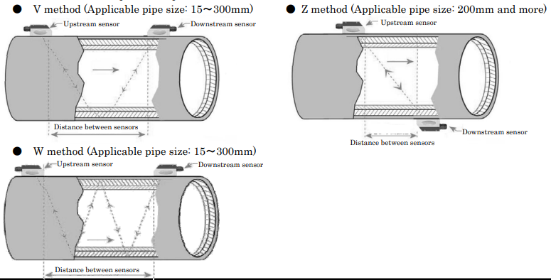
(1)Please select suitable installation method for piping condition in order to measure correctly. Please select from V
method, Z method and W method as below.
※ Extension rail as an option is required for Z method.
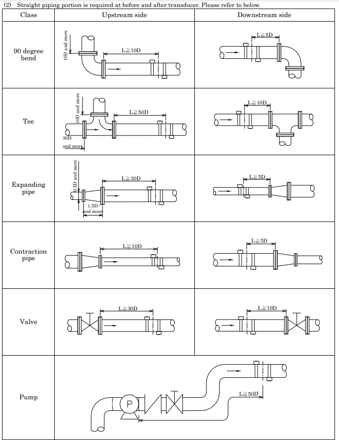
(2) Straight piping portion is required at before and after transducer. Please refer to below.
(3)Ambient temperature shall not exceed specification temperature. Less thermal variation is preferable.
(4)Please install to the pipe less obstacle of ultrasonic such as rust or scale. In case of impossibility, please set obstacle
as a liner, and measurement accuracy is equivalent of specification. However, please clean a pipe as possible.
(5)Space between pipe and liner makes difficulty of measurement because of less propagation of ultrasonic.
(6)Please select the place where pipe is filled by liquid while liquid does not flow. And also, please avoid to install the
place where may appear air bubbles.
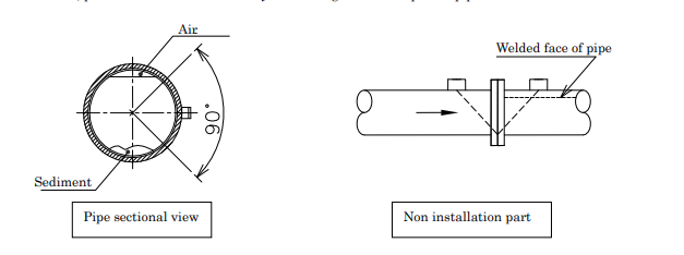
(7)Please avoid to install sensor at right above and right under of the pipe in order to avoid air pocket and sediments.
Sensor shall be installed side within 90 degree angle from horizontal. And also, please avoid installation at a joint of flange or welded part of pipe.
(8) Please apply acoustic coupler to sensor when install transducer. When apply the acoustic coupler, please be careful not to include air.
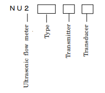
|
Model |
Code |
Specification |
||
|
NU2 |
|
Ultrasonic flow meter |
||
|
Type |
000 |
|
Clump-on type |
|
|
Transmitter |
SW |
|
Wall mount |
|
|
HD |
|
Hand held |
||
|
Transducer |
HSO HMO |
For pipe size: 15~ 100mm For pipe size: 50~ 600mm |
||
Related Products

Liquid Controls M-Series Meters (LC Meter)
View More
M5 — 1.5" LC Meter (275 lpm)
View More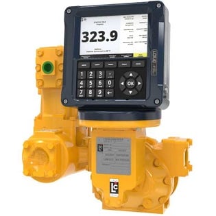
M7 — 2" LC Meter (500 LPM)
View More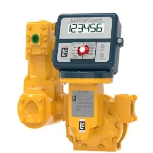
M10 — 2" LC Meter (550 LPM)
View More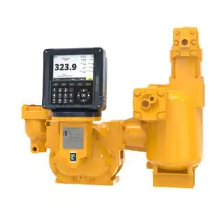
M15 — 3" LC Meter (1,000 LPM)
View More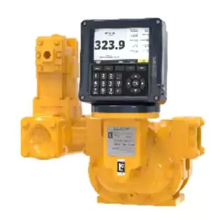
M25 — 3" LC Meter (1,150 LPM)
View More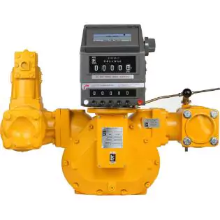
M30 — 4" LC Meter (1,325 LPM)
View More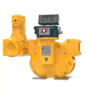
M40 — 4" LC Meter (2,300 LPM)
View More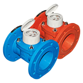

B-Meter WDE-K50 Water Flow Meter
View More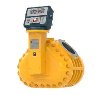
M60 — 6" LC Meter (2,800 LPM)
View More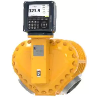
M80 — 6" LC Meter (2,800 LPM)
View More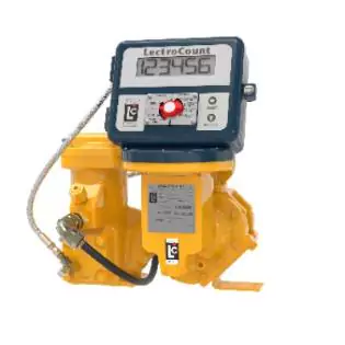
MA4 — 1" LC Meter (114 LPM)
View More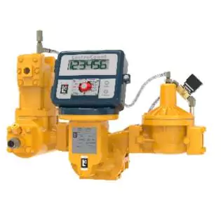
MA5 — 1.5" LC Meter (227 LPM)
View More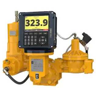
MA7 — 2" LC Meter (278 LPM)
View More
MA15 — 3" LC Meter (756 LPM)
View More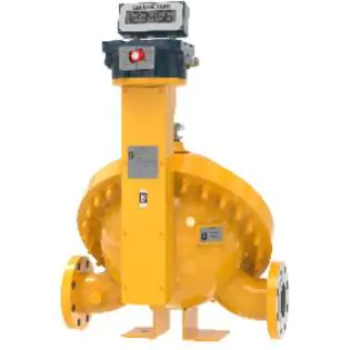
MSA30 — 3" LC Meter (1,325 LPM)
View More
MSA75 — 4" LC Meter (2650 LPM)
View More
MSAA30 — 3" LC Meter (1,325 LPM)
View More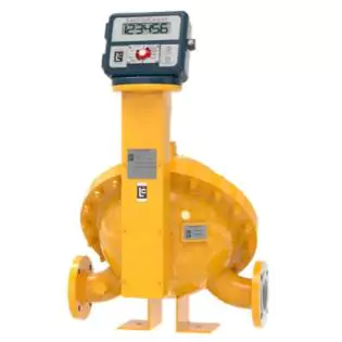
MSAA40 — 3" LC Meter (1,703 LPM)
View More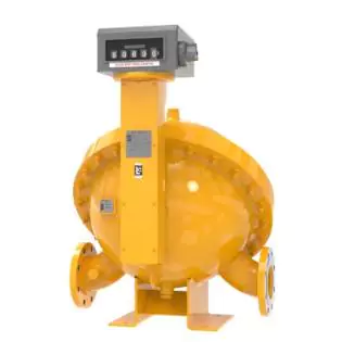
MSAA75 — 4" LC Meter (2,650 LPM)
View More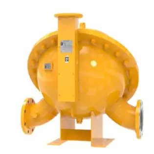
MSAA120 — 6" LC Meter (3785 LPM)
View More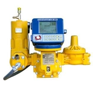
MA Series Meters
View More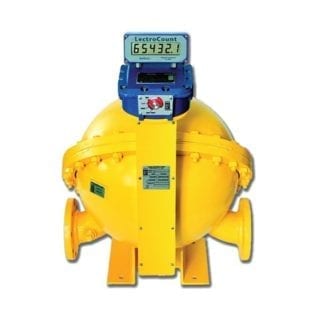
MS Series Meters
View More

Fill-Rite 807C1 Flow Meter
View More
Fill-Rite 900CD1.5 Flow Meter
View More
Fill-Rite 900CDP1.5 Flow Meters
View More
Fill-Rite 901CL1 Flow Meter
View More
Fill-Rite 901CL1.5 Flow Meter
View More
Fill-Rite FR1118A10 Flow Meter
View More
Fill-Rite TN860 Flow Meter
View More
Fill-Rite TS Aluminum Mechanical Flow Meter
View More
TS Precision Electronic Flow Meter
View More
B-Meter GSD8-I Single Jet Super Dry Meter
View More
B-Meter Hydrodigit Digital Water Meter
View More
B-Meter WDE-K30 Water Flow Meter
View More
GMDM-I Multi-jet Dry Dial Water Flow Meter
View More

Sotera In-Line Digital Meter (FR1118P10)
View More
Sotera In-Line Digital Turbine Meter
View More
Sotera Nutating Disc Flow Meter (825)
View More
Sotera Nutating Disc Flow Meter (825P)
View More
Sotera Nutating Disc Flow Meter (850)
View More
Sotera Nutating Disc Flow Meter (850P)
View More

Avery Hardoll DM Series Flow Meter
View More
Avery Hardoll BM Series Flow Meter
View More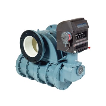
Avery Hardoll CM Series Meter
View More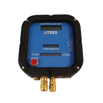
Masterload II
View More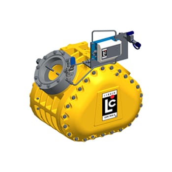
The Slipstream™ Density Measurement System (SDMS)
View More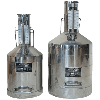
Calibration Cans
View More
Heavy Duty Provers
View More
Mobile Calibration Units
View More
Rotary Piston Flow Meter (BR Series)
View More
Rotary Piston Flow Meter (RS Series)
View More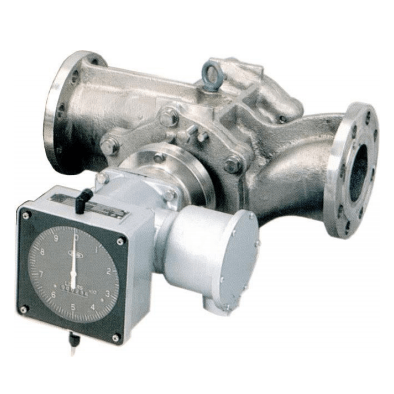
Sliding Vane Flow Meter (SS Series)
View More
Turbine Flow Meter (K Series)
View More
Air Eliminators
View More
Back Pressure Valves and Spring Loaded Check Valves
View More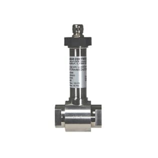
Differential Pressure Sensor
View More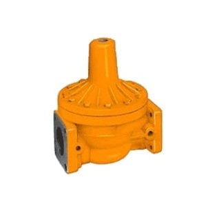
Differential Valves
View More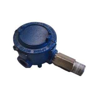
Electronic Air Detector (LC Sound)
View More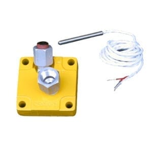
Electronic Temperature Volume Compensation (ETVC) Kit
View More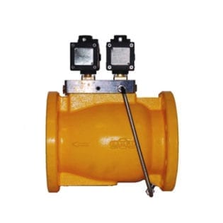
Hydraulic Valves (HPV)
View More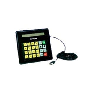
ElectroCount Electronic Registers Lap Pad
View More
Mechanical Valves (V-Series)
View More
Optical Air Eliminator
View More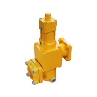
Pneumatic Valves (VP-Series)
View More
Pulse Output Device (POD)
View More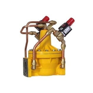
Solenoid Operated Valves
View More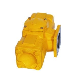
Strainers (F-Series)
View More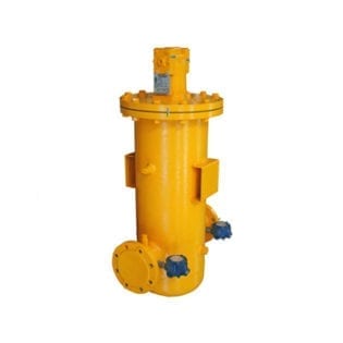
Strainers (FS-Series)
View More
Liquid Controls LectroCount LCR-II™ Electronic Register
View More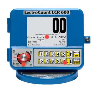
Liquid Controls LCR 600 Electronic Register
View More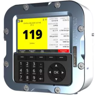
Liquid Control MASTERLOADx.iQ Zone 1 Rated Register
View More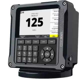
Liquid Controls LCR.iQ® Fueling Register
View More
B-meters Hydrosonic-M1 Ultrasonic smart meter
View More
B-meters HYDROSONIS-UP - Ultrasonic flow sensor
View More
B-meters CPR-M3-I Single jet, wet dial, direct reading with an anti-fraud ring
View More
B-meters CPR-RP Single jet semi-dry dial meter
View More
B-meters TAN-X5 Tangential irrigation water meter
View More
B-meters MAG-C Electromagnetic flow meter
View More
B-meters IWM-TX3 Wireless M-BUS radio module GMDM-I, GMB-I, GMB-RP-I and CPR-M3-I
View More
B-Meters IWM-TX4 Wireless M-BUS radio module WDE-K50
View More
B-meters RFM-RBT Wireless M-BUS receiver for Smartphones
View More
B-Meters IWM-MB4 Wired M-BUS module WDE-K50
View More
B-meters IWM-MB3 Wired M-BUS module GMDM-I, GMB-I, GMB-RP-I and CPR-M3-I
View More
B-meters IWM-PL4 Electronic pulse emitter module WDE-K50
View More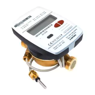
B-meters Hydrocal-M3 - Thermal Energy meter
View More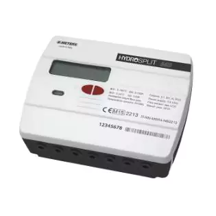
B-meters HYDROSPLIT-M3 Split thermal energy calculator
View More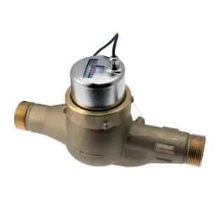
B-meters CMC-R - Multi jet super-dry 120Deg C with pulse output
View More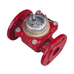
B-meters WDC-R - Thermal energy meter Woltmann
View More
B-meters HYDROSONIS-ULC Ultrasonic thermal energy meter
View More
B-meters HYDROCLIMA-RFM Wireless Heat cost allocator
View More
B-meters RFM-AMB Temperature and humidity sensor
View More
Fill-Rite TT10AN Digital Fuel Transfer Meter
View More

Sampi Gravity Meter
View More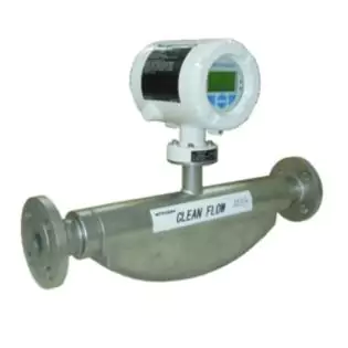
Nitto Seiko Mass Flow Meter
View More