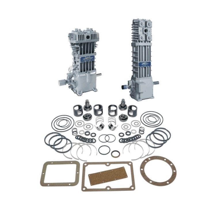

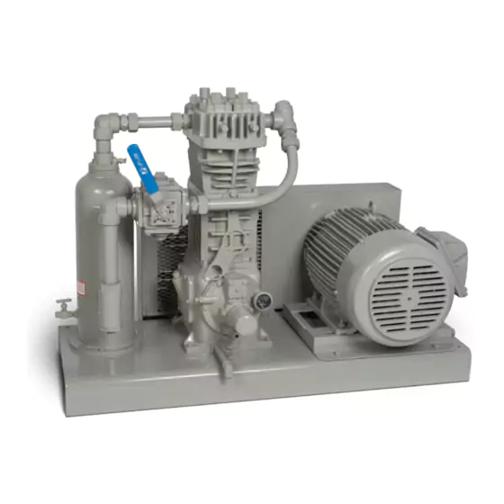
Corken 91 / F91 Compressor
|
Specifications |
Model |
|
91/F91 |
|
|
Bore of cylinder: inches (mm) |
3.0 (76.2) |
|
Stroke: inches (mm) |
2.5 (63.5) |
|
Piston displacement cfm (m3/hr) minimum @ 400 RPM axmimum @ 825 RPM |
4.1 (7.0) 8.4 (14.3) |
|
Maximum working pressure: psig (bar g) |
335 (23.1) |
|
Maximum brake horsepower: hp (kW) |
7.5 (5.6) |
|
Maximum rod load: lb (kg) |
3,600 (1,633) |
|
Maximum outlet temperature: °F (°C) |
350 (177) |
|
Minimum inlet temperature: °F (°C) |
-25 (-32) |
|
Bare unit weight: lb (kg) |
150 (68.0) |
|
Maximum flow-propane: gpm (m3/hr) |
50 (11.4) b |
|
Class 300 RF flange/DIN flange option |
Yes |
-
 Original Products
 -
 Warranty Against Defects
 -
 Returns & Refunds Policy
 -
 Ships Worldwide
 -
 Dedicate Support

- Performance
- Models
- Standard
- Mounting Details
- Propane Compressor Selection Table
- Ammonia Compressor Selection Table
- Parts Lists


Standard 107 Items
- Steel baseplate
- V-belt drive
- Adjustable driver side base
- Enclosed steel guard
- Suction and discharge
- pressure gauges
- 40 Micron strainer
- Non-lube 4-way valve
- Interconnecting piping
- Liquid trap as specified below
107 Mounting
Mechanical liquid trap with ball float
107A Mounting
Automatic liquid trap with one NEMA 7 liquid level switch
107B Mounting
Automatic liquid trap with two NEMA 7 liquid level switches
107F Mounting
107A or 107B with Class 300 RF flanged components and connections
Standard 109 Items
- Steel baseplate
- V-belt drive
- Adjustable driver side base
- Enclosed steel guard
- Suction and discharge pressure gauges
- 40 Micron strainer
- Non-lube 4-way valve
- Interconnecting piping
- Liquid trap as specified below
109 Mounting
Mechanical liquid trap with ball float
109A Mounting
Automatic liquid trap with one NEMA 7 liquid level switch
109B Mounting
Automatic liquid trap with two NEMA 7 liquid level switches
109F Mounting
109A or 109B with Class 300 RF flanged components and connections

|
Mounting Style |
Description |
Part No. |
Model Reference |
Ship Weight Compressor w/ Mounting |
|
103 Style |
Mounting includes steel baseplate, adjustable driver slide base, V-belt drive and enclosed belt guard. Pressure gauges are mounted on the compressor. |
103-2 (a) (b) |
91AJ3FBANSNN |
260 |
|
103HD |
Heavy duty version of the 103 mounting listed above |
103HD-2 (a) (b) |
91AJ3FBANHNN |
200 |
|
107 Style |
Mounting includes steel baseplate, mechanical liquid trap, non-lube 4-way valve, interconnecting piping, strainer, adjustable driver slide base, V-belt drive and enclosed belt guard. Pressure gauges are mounted on the compressor |
107-1 (a) (b) |
91AJ3FBANSNN |
350 |
|
107A Style |
Mounting includes steel baseplate, automatic liquid trap with NEMA 7 liquid level switch to stop compressor. Non-lube 4-way valve, interconnecting piping, strainer, adjustable driver slide base, V-belt drive and enclosed belt guard. Pressure gauges are mounted on the compressor. |
107A-1 (a) (b) |
91AJ3FBANSNN |
350 |
|
107B Style |
Mounting includes steel baseplate, ASME code liquid trap with two NEMA 7 liquid level switches for alarm and to stop compressor. Non-lube 4-way valve interconnecting piping, strainer and adjustable driver slide base, V-belt drive and enclosed belt guard. Pressure gauges are mounted on the compressor. |
107B-1 (a) (b) |
91AJ3FBANSNN |
675 |
|
107TR Style |
Mounting set up to be used as a transport unit. Mounting includes steel baseplate, mechanical liquid trap, non-lube 4-way valve, interconnecting piping, and strainer. |
107TR-70 |
91AE3FBANSNN |
150 |
|
109 Style |
Mounting includes steel baseplate, mechanical liquid trap, interconnecting piping, adjustable driver slide base, V-belt drive and enclosed belt guard. Pressure gauges mounted on the compressor. |
109-1 (a) (b) |
91AJ3FBANSNN |
330 |
|
109A Style |
Mounting includes steel baseplate, automatic liquid trap with NEMA 7 liquid level, switch to stop compressor, interconnecting piping, adjustable driver slide base, V-belt drive and enclosed belt guard. Pressure gauges are mounted on the compressor. |
109A-1 (a) (b) |
91AJ3FBANSNN |
330 |
|
109B Style |
Mounting includes steel baseplate, ASME automatic liquid trap with two NEMA 7, liquid level switches for alarm and to stop compressor, interconnecting piping, adjustable driver slide base, V-belt drive and enclosed belt guard. Pressure gauges are mounted on the compressor. |
109B-1 (a) (b) |
91AJ3FBANSNN |
650 |
Please note:
Above mountings are not applicable to the flanged compressors models F91–F691.
(a) Specify compressor speed
(b) Specify motor frame size (motor frequency / hertz)
(e) These units are not supplied with relief valves. A relief valve must be installed that is suitable for the service relief valve(s).
(f) Compressors must be equipped with extended crankshaft and special flywheel in order to use this mounting.
|
Service |
Capacity 1 |
Displacement cfm |
Compressor |
Driver Sheave Size P.D." 2 |
Driver Horsepower |
Piping Size 3 |
||||||
|
Liquid Transfer and Residual Vapor Recovery |
Liquid Transfer without Residual Vapor Recovery |
|||||||||||
|
Model |
RPM |
1,750 RPM |
1,450 RPM |
100°F |
80°F |
100°F |
80°F |
Vapor |
Liquid |
|||
|
Small bulk plants |
23 |
4 |
91 |
400 |
A 3.0 |
B 3.6 |
5 |
3 |
3 |
3 |
3/4 |
1-1/4 |
|
29 |
5 |
91 |
505 |
B 3.8 |
B 4.6 |
5 |
5 |
5 |
5 |
3/4 |
1-1/4 |
|
|
34 |
6 |
91 |
590 |
B 4.6 |
B 5.6 |
5 |
5 |
5 |
5 |
1 |
1-1/4 |
|
|
40 |
7 |
91 |
695 |
B 5.4 |
B 6.6 |
5 |
5 |
5 |
5 |
1 |
1-1/2 |
|
|
39 |
7 |
291 |
345 |
A 3.0 |
A 3.6 |
3 |
3 |
3 |
3 |
1 |
1-1/2 |
|
|
Unloading single tank car or transport |
45 |
8 |
91 |
800 |
B 6.2 |
B 7.4 |
7-1/2 |
7-1/2 |
7-1/2 |
7-1/2 |
1 |
1-1/2 |
|
44 |
8 |
291 |
390 |
A 3.4 |
B 4.0 |
5 |
3 |
3 |
3 |
1 |
1-1/2 |
|
|
50 |
9 |
291 |
435 |
A 3.8 |
B 4.6 |
5 |
5 |
3 |
3 |
1 |
1-1/2 |
|
|
56 |
10 |
291 |
490 |
B 4.4 |
B 5.2 |
5 |
5 |
5 |
5 |
1 |
2 |
|
|
61 |
11 |
291 |
535 |
B 4.8 |
B 5.8 |
5 |
5 |
5 |
5 |
1 |
2 |
|
|
66 |
12 |
291 |
580 |
B 5.2 |
B 6.2 |
7-1/2 |
5 |
5 |
5 |
1 |
2 |
|
|
71 |
13 |
291 |
625 |
B 5.6 |
B 6.6 |
7-1/2 |
5 |
7-1/2 |
5 |
1-1/4 |
2 |
|
|
79 |
14 |
291 |
695 |
B 6.2 |
B 7.4 |
7-1/2 |
7-1/2 |
7-1/2 |
7-1/2 |
1-1/4 |
2 |
|
|
84 |
15 |
291 |
735 |
B 6.6 |
B 8.0 |
10 |
7-1/2 |
10 |
7-1/2 |
1-1/4 |
2-1/2 |
|
|
84 |
15 |
491 |
345 |
A 3.0 |
A 3.6 |
7-1/2 |
7-1/2 |
5 |
5 |
1-1/4 |
2-1/2 |
|
|
89 |
16 |
291 |
780 |
B 7.0 |
B 8.6 |
10 |
10 |
10 |
10 |
1-1/4 |
2-1/2 |
|
|
89 |
16 |
491 |
370 |
A 3.2 |
A 3.8 |
7-1/2 |
7-1/2 |
7-1/2 |
5 |
1-1/4 |
2-1/2 |
|
|
Unloading two or more tank cars at one time or large transport with excess flow valves of adequate capacity |
95 |
17 |
491 |
390 |
A 3.4 |
B 4.0 |
7-1/2 |
7-1/2 |
7-1/2 |
7-1/2 |
1-1/4 |
3 |
|
101 |
18 |
491 |
415 |
A 3.6 |
B 4.4 |
10 |
7-1/2 |
7-1/2 |
7-1/2 |
1-1/4 |
3 |
|
|
106 |
19 |
491 |
435 |
A 3.8 |
B 4.6 |
10 |
7-1/2 |
7-1/2 |
7-1/2 |
1-1/4 |
3 |
|
|
108 |
20 |
491 |
445 |
B 4.0 |
B 4.8 |
10 |
7-1/2 |
7-1/2 |
7-1/2 |
1-1/4 |
3 |
|
|
114 |
21 |
491 |
470 |
B 4.2 |
B 5.0 |
10 |
7-1/2 |
7-1/2 |
7-1/2 |
1-1/4 |
3 |
|
|
119 |
22 |
491 |
490 |
B 4.4 |
B 5.2 |
10 |
10 |
7-1/2 |
7-1/2 |
1-1/4 |
3 |
|
|
125 |
23 |
491 |
515 |
B 4.6 |
B 5.6 |
10 |
10 |
10 |
7-1/2 |
1-1/4 |
3 |
|
|
130 |
24 |
491 |
535 |
B 4.8 |
B 5.8 |
15 |
10 |
10 |
10 |
1-1/4 |
3 |
|
|
136 |
25 |
491 |
560 |
B 5.0 |
B 6.0 |
15 |
10 |
10 |
10 |
1-1/4 |
3 |
|
|
141 |
26 |
491 |
580 |
B 5.2 |
B 6.2 |
15 |
10 |
10 |
10 |
1-1/4 |
3 |
|
|
147 |
27 |
491 |
605 |
B 5.4 |
B 6.4 |
15 |
10 |
15 |
10 |
1-1/4 |
3 |
|
|
152 |
28 |
491 |
625 |
B 5.6 |
B 6.6 |
15 |
15 |
15 |
15 |
1-1/2 |
3 |
|
|
158 |
29 |
491 |
650 |
B 5.8 |
B 7.0 |
15 |
15 |
15 |
15 |
1-1/2 |
3 |
|
|
163 |
30 |
491 |
670 |
B 6.0 |
|
15 |
15 |
15 |
15 |
1-1/2 |
3 |
|
|
163 |
30 |
691 |
400 |
B 4.4 |
B 5.2 |
15 |
15 |
10 |
10 |
1-1/2 |
3 |
|
|
168 |
31 |
491 |
695 |
B 6.2 |
B 7.4 |
15 |
15 |
15 |
15 |
1-1/2 |
3 |
|
|
171 |
31 |
691 |
420 |
B 4.6 |
B 5.6 |
15 |
15 |
10 |
10 |
1-1/2 |
3 |
|
|
179 |
32 |
491 |
740 |
B 6.6 |
B 8.0 |
15 |
15 |
15 |
15 |
1-1/2 |
3 |
|
|
178 |
32 |
691 |
440 |
B 4.8 |
B 5.8 |
15 |
15 |
10 |
10 |
1-1/2 |
3 |
|
|
186 |
34 |
691 |
455 |
B 5.0 |
B 6.0 |
15 |
15 |
15 |
10 |
1-1/2 |
3 |
|
|
193 |
35 |
691 |
475 |
B 5.2 |
B 6.2 |
15 |
15 |
15 |
10 |
1-1/2 |
3 |
|
|
200 |
36 |
691 |
495 |
B 5.4 |
B 6.4 |
15 |
15 |
15 |
15 |
1-1/2 |
3 |
|
|
Unloading large tank cars, multiple vessels, barges or terminals |
208 |
38 |
691 |
510 |
B 5.6 |
B 6.8 |
20 |
15 |
15 |
15 |
1-1/2 |
4 |
|
215 |
39 |
691 |
530 |
B 5.8 |
B 7.0 |
20 |
15 |
15 |
15 |
1-1/2 |
4 |
|
|
223 |
41 |
691 |
550 |
B 6.0 |
A 7.0 |
20 |
15 |
15 |
15 |
1-1/2 |
4 |
|
|
230 |
42 |
691 |
565 |
B 6.2 |
B 7.4 |
20 |
15 |
15 |
15 |
2 |
4 |
|
|
237 |
43 |
691 |
585 |
B 6.4 |
A 7.4 |
20 |
15 |
15 |
15 |
2 |
4 |
|
|
245 |
45 |
691 |
605 |
B 6.6 |
B 8.0 |
20 |
15 |
15 |
15 |
2 |
4 |
|
|
252 |
46 |
691 |
620 |
B 6.8 |
|
20 |
20 |
15 |
15 |
2 |
4 |
|
|
260 |
47 |
691 |
640 |
B 7.0 |
A 8.2 |
20 |
20 |
20 |
15 |
2 |
4 |
|
|
275 |
48 |
691 |
675 |
B 7.4 |
B 8.6 |
25 |
20 |
20 |
20 |
2 |
4 |
|
|
297 |
54 |
691 |
730 |
B 8.0 |
B 9.4 |
25 |
20 |
20 |
20 |
2 |
4 |
|
|
319 |
58 |
691 |
785 |
B 8.6 |
|
25 |
20 |
25 |
20 |
2 |
4 |
|
|
334 |
60 |
691 |
820 |
TB 9.0 |
A 10.6 |
30 |
25 |
25 |
20 |
2 |
4 |
|
|
452 |
82 |
D/FD891 |
580 |
5V 7.1 |
5V 8.5 |
30 |
30 |
30 |
30 |
3 |
6 |
|
|
623 |
113 |
D/FD891 |
800 |
5V 9.75 |
5V 11.8 |
|
40 |
40 |
30 |
3 |
6 |
|
|
Service |
Capacity 1 |
Displacement cfm |
Compressor |
Driver Sheave Size P.D." 2 |
Driver Horsepower |
Piping Size 3 |
||||||
|
Liquid Transfer and Residual Vapor Recovery |
Liquid Transfer without Residual Vapor Recovery |
|||||||||||
|
Model |
RPM |
1,750 RPM |
1,450 RPM |
100°F |
80°F |
100°F |
80°F |
Vapor |
Liquid |
|||
|
Small bulk plants |
23 |
4 |
91 |
400 |
A 3.0 |
B 3.6 |
5 |
3 |
3 |
3 |
3/4 |
1-1/4 |
|
29 |
5 |
91 |
505 |
B 3.8 |
B 4.6 |
5 |
5 |
5 |
3 |
3/4 |
1-1/4 |
|
|
34 |
6 |
91 |
590 |
B 4.6 |
B 5.6 |
5 |
5 |
5 |
5 |
1 |
1-1/4 |
|
|
40 |
7 |
91 |
695 |
B 5.4 |
B 6.6 |
5 |
5 |
5 |
5 |
1 |
1-1/2 |
|
|
43 |
7 |
291 |
345 |
A 3.0 |
A 3.6 |
5 |
3 |
3 |
3 |
1 |
1-1/2 |
|
|
Unloading single tank car or transport |
46 |
8 |
91 |
800 |
B 6.2 |
B 7.4 |
7-1/2 |
5 |
5 |
5 |
1 |
1-1/2 |
|
45 |
8 |
291 |
390 |
A 3.4 |
B 4.0 |
5 |
3 |
3 |
3 |
1 |
1-1/2 |
|
|
50 |
9 |
291 |
435 |
A 3.8 |
B 4.6 |
5 |
5 |
3 |
3 |
1 |
1-1/2 |
|
|
56 |
10 |
291 |
490 |
B 4.4 |
B 5.2 |
5 |
5 |
5 |
3 |
1 |
2 |
|
|
62 |
11 |
291 |
535 |
B 4.8 |
B 5.8 |
7-1/2 |
5 |
5 |
5 |
1 |
2 |
|
|
67 |
12 |
291 |
580 |
B 5.2 |
B 6.2 |
7-1/2 |
5 |
5 |
5 |
1 |
2 |
|
|
72 |
13 |
291 |
625 |
B 5.6 |
B 6.6 |
7-1/2 |
5 |
5 |
5 |
1-1/4 |
2 |
|
|
80 |
14 |
291 |
695 |
B 6.2 |
B 7.4 |
7-1/2 |
7-1/2 |
7-1/2 |
5 |
1-1/4 |
2 |
|
|
85 |
15 |
291 |
735 |
B 6.6 |
B 8.0 |
10 |
7-1/2 |
7-1/2 |
7-1/2 |
1-1/4 |
2-1/2 |
|
|
85 |
15 |
491 |
345 |
A 3.0 |
A 3.6 |
7-1/2 |
7-1/2 |
5 |
5 |
1-1/4 |
2-1/2 |
|
|
90 |
16 |
291 |
780 |
B 7.0 |
B 8.6 |
10 |
7-1/2 |
7-1/2 |
7-1/2 |
1-1/4 |
2-1/2 |
|
|
90 |
16 |
491 |
370 |
A 3.2 |
A 3.8 |
10 |
7-1/2 |
5 |
5 |
1-1/4 |
2-1/2 |
|
|
Unloading two or more tank cars at one time or large transport with excess flow valves of adequate capacity |
96 |
17 |
491 |
390 |
A 3.4 |
B 4.0 |
10 |
7-1/2 |
5 |
5 |
1-1/4 |
3 |
|
102 |
18 |
491 |
415 |
A 3.6 |
B 4.4 |
10 |
7-1/2 |
7-1/2 |
7-1/2 |
1-1/4 |
3 |
|
|
107 |
19 |
491 |
435 |
A 3.8 |
B 4.6 |
10 |
7-1/2 |
7-1/2 |
7-1/2 |
1-1/4 |
3 |
|
|
110 |
20 |
491 |
445 |
B 4.0 |
B 4.8 |
10 |
7-1/2 |
7-1/2 |
7-1/2 |
1-1/4 |
3 |
|
|
115 |
21 |
491 |
470 |
B 4.2 |
B 5.0 |
10 |
7-1/2 |
7-1/2 |
7-1/2 |
1-1/4 |
3 |
|
|
120 |
22 |
491 |
490 |
B 4.4 |
B 5.2 |
15 |
10 |
7-1/2 |
7-1/2 |
1-1/4 |
3 |
|
|
126 |
23 |
491 |
515 |
B 4.6 |
B 5.6 |
15 |
10 |
7-1/2 |
7-1/2 |
1-1/4 |
3 |
|
|
131 |
24 |
491 |
535 |
B 4.8 |
B 5.8 |
15 |
10 |
10 |
7-1/2 |
1-1/4 |
3 |
|
|
138 |
25 |
491 |
560 |
B 5.0 |
B 6.0 |
15 |
10 |
10 |
7-1/2 |
1-1/4 |
3 |
|
|
142 |
26 |
491 |
580 |
B 5.2 |
B 6.2 |
15 |
10 |
10 |
7-1/2 |
1-1/4 |
3 |
|
|
148 |
27 |
491 |
605 |
B 5.4 |
B 6.4 |
15 |
10 |
10 |
10 |
1-1/4 |
3 |
|
|
153 |
28 |
491 |
625 |
B 5.6 |
B 6.6 |
15 |
10 |
10 |
10 |
1-1/2 |
3 |
|
|
160 |
29 |
491 |
650 |
B 5.8 |
B 7.0 |
15 |
15 |
10 |
10 |
1-1/2 |
3 |
|
|
165 |
30 |
491 |
670 |
B 6.0 |
|
15 |
15 |
15 |
10 |
1-1/2 |
3 |
|
|
165 |
30 |
691 |
400 |
B 4.4 |
B 5.2 |
15 |
15 |
10 |
10 |
1-1/2 |
3 |
|
|
170 |
31 |
491 |
695 |
B 6.2 |
B 7.4 |
15 |
15 |
15 |
10 |
1-1/2 |
3 |
|
|
173 |
31 |
691 |
420 |
B 4.6 |
B 5.6 |
15 |
15 |
10 |
10 |
1-1/2 |
3 |
|
|
181 |
32 |
491 |
740 |
B 6.6 |
B 8.0 |
15 |
15 |
15 |
15 |
1-1/2 |
3 |
|
|
180 |
32 |
691 |
440 |
B 4.8 |
B 5.8 |
15 |
15 |
10 |
10 |
1-1/2 |
3 |
|
|
188 |
34 |
691 |
455 |
B 5.0 |
B 6.0 |
20 |
15 |
10 |
10 |
1-1/2 |
3 |
|
|
195 |
35 |
691 |
475 |
B 5.2 |
B 6.2 |
20 |
15 |
10 |
10 |
1-1/2 |
3 |
|
|
203 |
36 |
691 |
495 |
B 5.4 |
B 6.4 |
20 |
15 |
15 |
10 |
1-1/2 |
3 |
|
|
Unloading large tank cars, multiple vessels, barges or terminals |
211 |
38 |
691 |
510 |
B 5.6 |
B 6.8 |
20 |
15 |
15 |
10 |
1-1/2 |
4 |
|
218 |
39 |
691 |
530 |
B 5.8 |
B 7.0 |
20 |
15 |
15 |
15 |
1-1/2 |
4 |
|
|
226 |
41 |
691 |
550 |
B 6.0 |
A 7.0 |
20 |
15 |
15 |
15 |
1-1/2 |
4 |
|
|
233 |
42 |
691 |
565 |
B 6.2 |
B 7.4 |
20 |
15 |
15 |
15 |
2 |
4 |
|
|
240 |
43 |
691 |
585 |
B 6.4 |
A 7.4 |
20 |
20 |
15 |
15 |
2 |
4 |
|
|
248 |
45 |
691 |
605 |
B 6.6 |
B 8.0 |
20 |
20 |
15 |
15 |
2 |
4 |
|
|
255 |
45 |
691 |
620 |
B 6.8 |
|
25 |
20 |
15 |
15 |
2 |
4 |
|
|
263 |
47 |
691 |
640 |
B 7.0 |
A 8.2 |
25 |
20 |
15 |
15 |
2 |
4 |
|
|
278 |
48 |
691 |
675 |
B 7.4 |
B 8.6 |
25 |
20 |
15 |
15 |
2 |
4 |
|
|
301 |
54 |
691 |
730 |
B 8.0 |
B 9.4 |
25 |
20 |
20 |
15 |
2 |
4 |
|
|
323 |
58 |
691 |
785 |
B 8.6 |
|
30 |
25 |
20 |
20 |
2 |
4 |
|
|
338 |
60 |
691 |
820 |
TB 9.0 |
A 10.6 |
30 |
25 |
20 |
20 |
2 |
4 |
|
|
459 |
82 |
D/FD891 |
580 |
5V 7.1 |
5V 8.5 |
40 |
30 |
30 |
30 |
3 |
6 |
|
|
633 |
113 |
D/FD891 |
800 |
5V 9.75 |
5V 11.8 |
|
40 |
40 |
30 |
3 |
6 |
|
Compressor repair Kits
|
part number |
3549-x1 |
|
model number |
90J3, 91J3 |
|
Suction valve assembly |
3483-1X |
|
discharge valve assembly |
3485-X |
|
Valve cage |
— |
|
Connecting rod bearing (pair) |
1367 |
|
Packing set |
1452-1X1 |
|
Piston rings |
1772 (3)2 |
|
ring expanders |
1775 (3)2 |
|
Gasket set1 |
2526-XA1 |
|
O-ring1 |
— |
|
O-ring1 |
— |
|
O-ring1 |
— |
|
Oil seal |
3259 |
|
Oil seal |
— |
|
Adapter plate gasket |
— |
Model 91 gasket set (2526-xA)
|
part number |
description |
Quantity |
|
2-235A |
O-ring, buna-N |
2 |
|
2526 |
Crankcase gasket |
1 |
|
2717 |
Valve gasket, aluminum |
2 |
|
2729 |
Crankcase inspection plate gas |
1 |
|
2-031A |
O-ring, buna-N |
2 |
|
2244 |
Inspection plate gasket |
1 |
|
2716 |
Valve cap gasket, aluminum |
2 |
|
2725 |
bearing carrier gasket |
1 |
Flywheel Assembly bill of materials
|
Assembly number |
Assembly name |
|
3271-X2 |
Flywheel assembly (flywheel, hub, and three bolts) |
|
3271 |
Flywheel: 14" O.d., 2 groove |
|
H SF-1.125 |
Hub with three bolts and lockwashers |
Packing Assembly
|
ref no. |
part no. |
description |
Qty |
|
1. |
2242 |
Cylinder |
1 |
|
2. |
2-235_a |
O-ring for cylinder |
1 |
|
3. |
5000-137 |
retainer ring |
1 |
|
4. |
1012 |
Washer |
1 |
|
5. |
1628 |
Packing spring |
1 |
|
6. |
1714 |
Packing box washer |
1 |
|
7. |
1453-1 |
Male packing ring |
1 |
|
8. |
1454b |
Packing ring |
8 |
|
9. |
1452-1 |
Female packing ring |
1 |
|
10. |
2240 |
Crosshead guides |
1 |
|
11. |
1387 |
Adjusting screw |
1 |
|
12. |
2526 |
Crankcase gasket |
1 |
|
13. |
1452-1X1 |
Packing set |
1 |
|
Assembly number |
Assembly name |
|
1132-X2 |
Crosshead - piston-rod assembly |
|
1452-2X1d |
Packing set (alloy 50) with 1452-1, 1453-1, 1454-2 (8), 1626, 1714 |
Piston Assembly number 1983-x
|
ref no. |
part no. |
description |
Qty |
|
1. |
7002-010OC100A |
Screw, socket head |
4 |
|
7207-010A |
Lock washer |
4 |
|
|
2. |
1983 |
Head, iron |
1 |
|
3. |
1775 |
ring expander |
3 |
|
4. |
1772 |
Piston ring |
3 |
|
5. |
1482 |
Locknut |
1 |
|
6. |
1483 |
Lock pin |
1 |
|
7. |
1984 |
Piston platform |
1 |
|
8. |
1528 |
Shim washer, thick |
As req. |
|
1528-1 |
Shim washer, thin |
||
|
9. |
1527 |
Thrust washer |
1 |
Four-Way Valve Repair Kits
|
description |
trim |
part number |
Connection sizes |
|
Four-Way Valve repair Kits |
PTFE and buna-N trim |
3122-X |
1" |
|
3123-X |
1¼" |
||
|
3130-X |
2" |
Head and valve bill of materials
|
ref no. |
part no. |
description |
|
1. |
2374 |
Head model 91 |
|
2374-Xa |
Head assy. for model 91 (spec 3) |
|
|
2374-X1 |
Head assy. for model 91 (spec 4) |
|
|
2. |
4302 |
Head model F91 (ANSI flange) |
|
3. |
7001-037 NC100A |
bolt, 3/8-16 x 1" Gr.5 hex head |
|
4. |
2-235_c |
O-ring |
|
5. |
2714-1 |
Valve cap |
|
6. |
2-031_c |
O-ring |
|
7. |
2715 |
Holddown screw |
|
8. |
3483-1X |
Suction valve assy. (spec 3) |
|
3483-1X1b |
Same as above but with copper gaskets |
|
|
3483-1X2b |
Same as above but with iron-lead gaskets |
|
|
9. |
3483-X |
Suction valve assy. (spec 4) |
|
3483-X1b |
Same as above but with copper gaskets |
|
|
3483-X2b |
Same as above but with iron-lead gaskets |
|
|
10. |
3485-X |
discharge valve assy. (all specs) |
|
3485-X1b |
Same as above but with copper gaskets |
|
|
3485-X2b |
Same as above but with iron-lead gaskets |
|
|
11. |
2717 |
Valve gasket (aluminum) |
|
2717-1b |
Valve gasket (copper) |
|
|
2717-2b |
Valve gasket (iron-lead) |
|
|
12. |
5000-77 |
retainer ring (spec 3) |
|
13. |
3977 |
Suction valve relief housing (spec 3) |
|
14. |
1411 |
Spring (spec 3) |
|
15. |
1410 |
ball (spec 3) |
|
16. |
3483-1 |
Suction valve seat (spec 3) |
|
17. |
3972 |
Suction valve plate (spec 3) |
|
18. |
4009 |
Suction spring (spec 3) |
|
19. |
3484 |
Suction valve bumper (spec 3) |
|
20. |
3483 |
Suction valve seat (spec 4) |
|
21. |
3972 |
Suction valve plate (spec 4) |
|
22. |
4009 |
Suction spring (spec 4) |
|
23. |
3484 |
Suction valve bumper (spec 4) |
|
24. |
3486 |
discharge valve bumper |
|
25. |
4008 |
discharge spring |
|
26. |
3973 |
discharge valve plate |
|
27. |
3485 |
discharge valve seat |
Crankcase Assembly
|
ref no. |
part no. |
description |
|
1. |
3259 |
Oil seal |
|
2. |
1483 |
roll pin - 1/8 x 1" |
|
3. |
7001-037NC075A |
Hex head 3/8-16 x 3/4", Gr 5 |
|
4. |
3260 |
bearing carrier |
|
5. |
2796 |
breather ball |
|
6. |
1279-X |
O-ring (part of bearing cap assembly) |
|
7. |
1279-X |
breather cap assembly (with O-ring - ref. no. 6) |
|
8. |
2725 |
bearing carrier gasket |
|
9. |
1807 |
roll pin - 1/8 x 5/8" |
|
10. |
2718 |
bearing cup |
|
11. |
2723 |
Oil circulating ring |
|
12. |
2476 |
Crankshaft |
|
13. |
2719 |
bearing cone |
|
14. |
2289 |
Flywheel key |
|
15. |
2290 |
Oil ring retainer washer |
|
16. |
2554a |
Crankcase |
|
17. |
1661 |
Pipe plug - 3/8 NPT sq. or hex |
|
18. |
2729 |
Inspection plate gasket |
|
19. |
2728 |
Crankcase inspection plate |
|
20. |
2-112_c |
O-ring |
|
21. |
1368-X1 |
Oil bayonet assembly (with O-ring) |
|
22. |
2721 |
bearing adjustment shim (0.005) |
|
2721-1 |
bearing adjustment shim (0.007) |
|
|
2721-2 |
bearing adjustment shim (0.020) |
|
|
23. |
2720 |
bearing cap |
Other Assemblies
|
Assembly number |
Assembly name |
|
2476-X |
Crankshaft assembly with 2476, 2290 and 2719 |
|
2476-SXb |
Extended crankshaft assembly with 2719 (2) and 2290, (optional) |
|
3260-X |
bearing carrier assembly with 3260, 2718, 3259, 1279-X, 2-111, 1483, 2796 and 1807 |
|
3271-X2b |
Flywheel assembly 14" - 2 groove with H SF-1.125 and 3271 |
Connecting rod Assembly
|
ref no. |
part no. |
description |
|
1. |
1132-X2 |
Crosshead assembly |
|
2. |
1498 |
retainer ring |
|
3. |
2505 |
Wrist pin |
|
4. |
1846-Xa,b |
Wrist pin bushing |
|
5. |
1599b |
bolt |
|
6. |
1889-1X |
Connecting rod assembly |
|
7. |
1889-1b |
Connecting rod |
|
8. |
1367b |
Connecting rod bearing |
|
9. |
2011b |
dipper |
|
10. |
1600b,c |
Nut |
Related Products
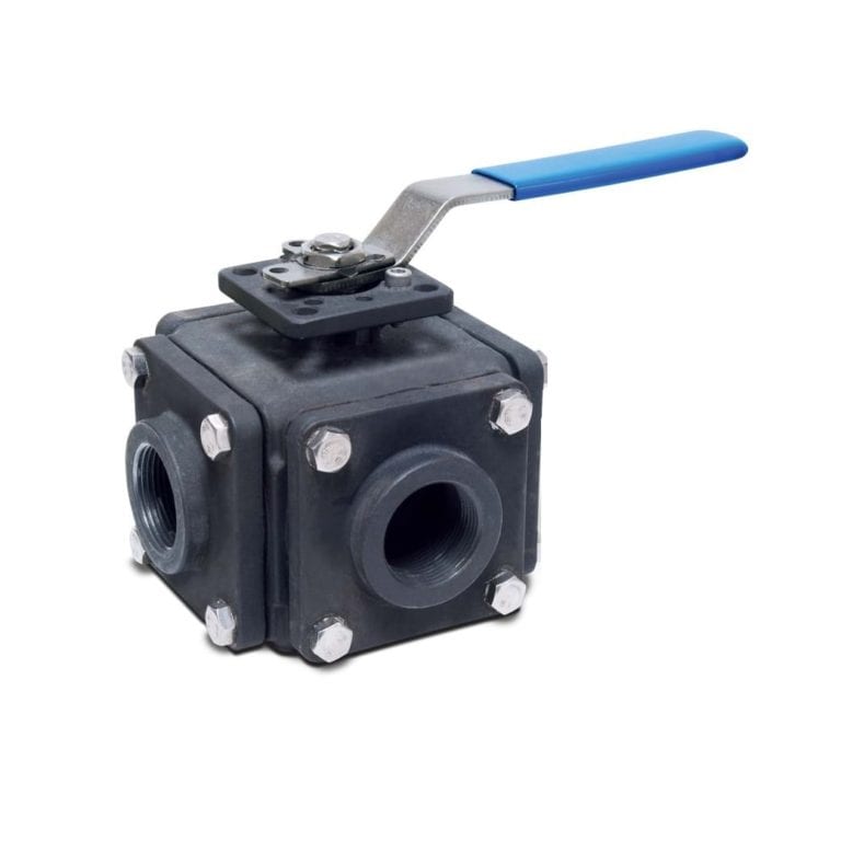
4-Way Valve (Non-Lubricated)
View More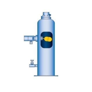
Automatic Liquid Trap
View More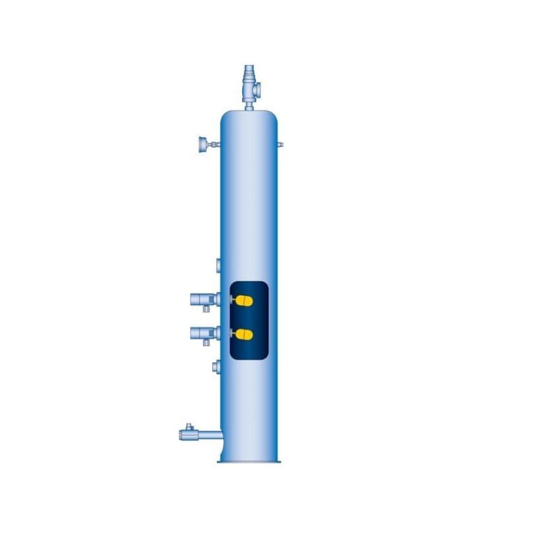
Automatic Liquid Trap (ASME Code-Stamped)
View More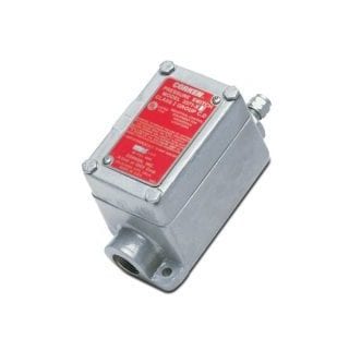
Low-Oil-Pressure Switch
View More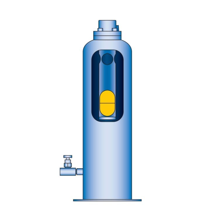
Mechanical Liquid Trap
View More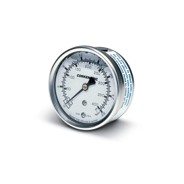
Pressure Gauges
View More
Strainer
View More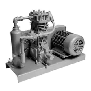
Corken 291 / F291 Compressor
View More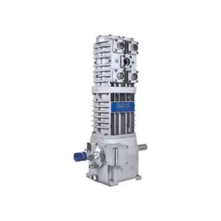
Corken 491 Compressor
View More
Corken 691 Compressor
View More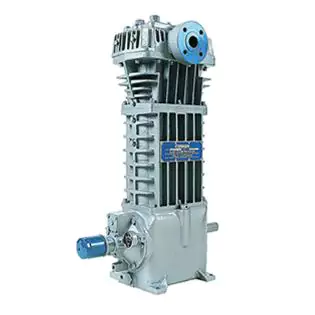
Corken FD891 Compressor
View More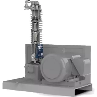
Corken UL Certified Plant Oil Extraction Compressor System
View More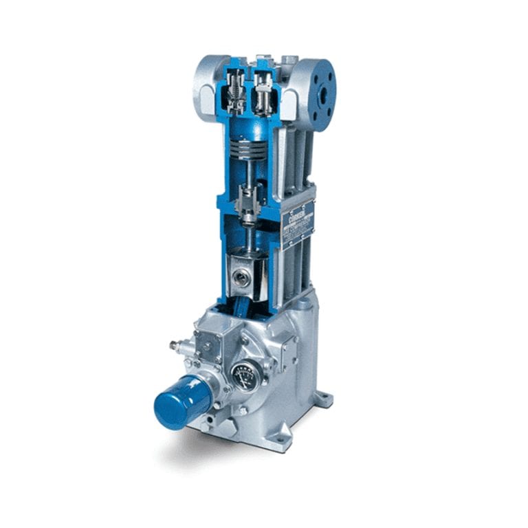
LPG Reciprocating Compressor
View More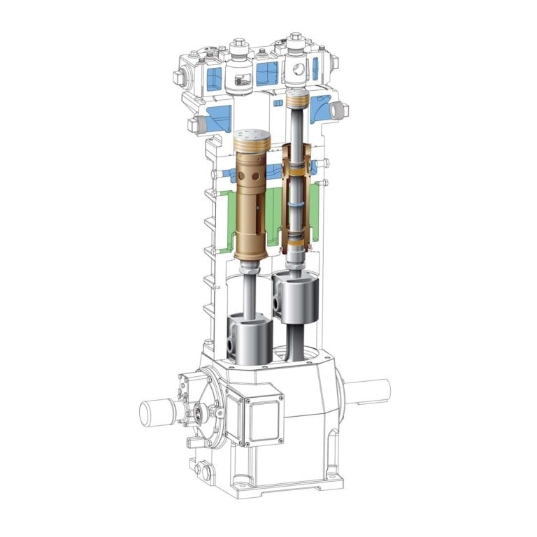
D-Style Oil-Free Reciprocating Compressors
View More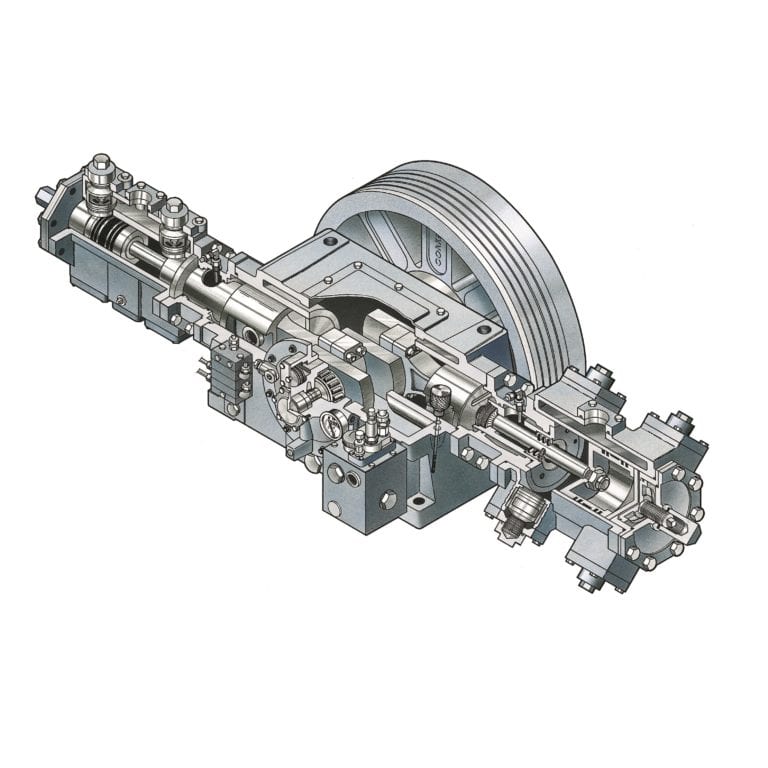
Single Packed Reciprocating Compressors (Non Oil Free)
View More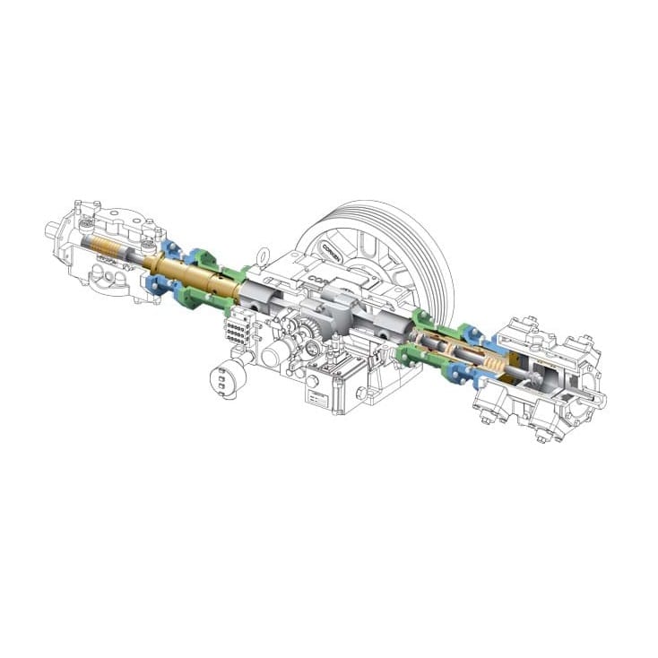
Triple Packed Reciprocating Compressors (Oil Free)
View More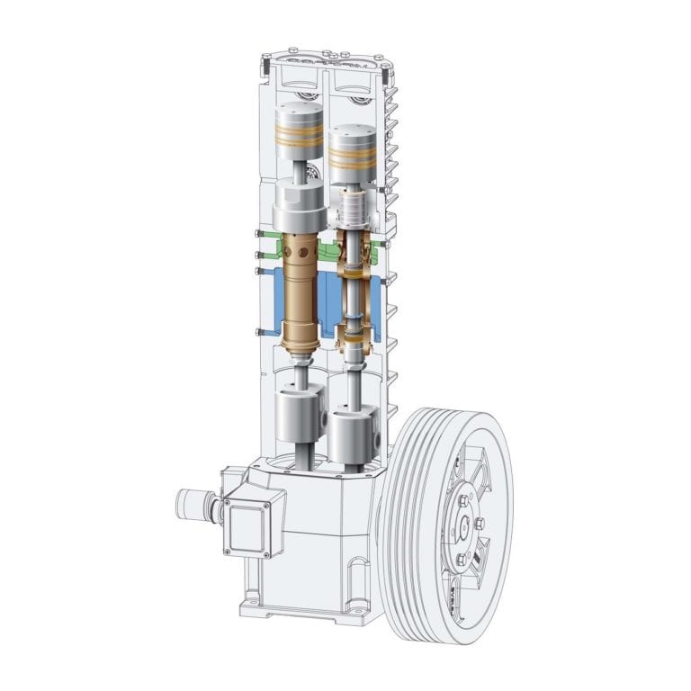
T-Style Oil-Free Reciprocating Compressors
View More