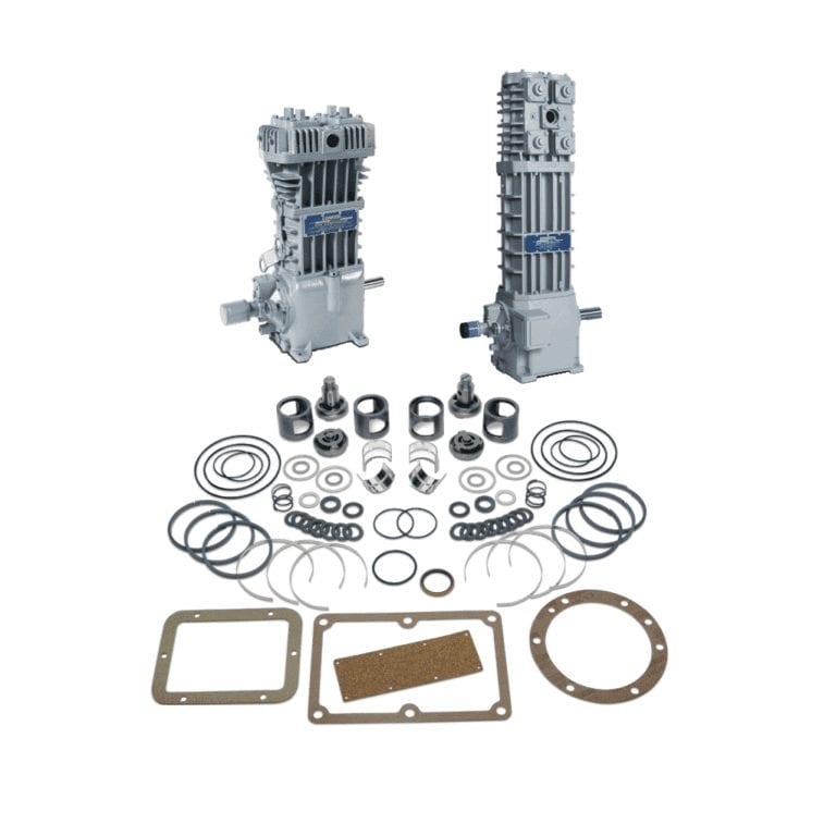

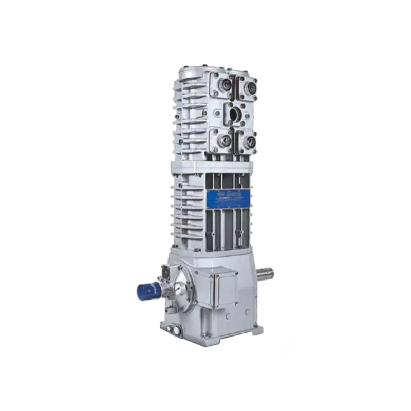
Corken 491 Compressor
|
Specifications |
Model |
|
491/F491 |
|
|
Bore of cylinder: inches (mm) |
4.0 (101.6) |
|
Stroke: inches (mm) |
3.0 (76.2) |
|
Piston displacement cfm (m3/hr) minimum @ 400 RPM axmimum @ 825 RPM |
17.5 (29.7) 36.0 (61.2) |
|
Maximum working pressure: psig (bar g) |
335 (23.1) |
|
Maximum brake horsepower: hp (kW) |
15 (11) |
|
Maximum rod load: lb (kg) |
4,000 (1,814) |
|
Maximum outlet temperature: °F (°C) |
350 (177) |
|
Minimum inlet temperature: °F (°C) |
-25 (-32) |
|
Bare unit weight: lb (kg) |
390 (176.9) |
|
Maximum flow-propane: gpm (m3/hr) |
215 (48.8) b |
|
Class 300 RF flange/DIN flange option |
Yes |
-
 Original Products
 -
 Warranty Against Defects
 -
 Returns & Refunds Policy
 -
 Ships Worldwide
 -
 Dedicate Support

- Performance
- Models
- Standard Mounting
- Mounting
- Propane Compressor Selection Table
- Ammonia Compressor Selection Table
- Parts Lists
- Description


Standard 107 Items
- Steel baseplate
- V-belt drive
- Adjustable driver side base
- Enclosed steel guard
- Suction and discharge
- pressure gauges
- 40 Micron strainer
- Non-lube 4-way valve
- Interconnecting piping
- Liquid trap as specified below
107 Mounting
Mechanical liquid trap with ball float
107A Mounting
Automatic liquid trap with one NEMA 7 liquid level switch
107B Mounting
Automatic liquid trap with two NEMA 7 liquid level switches
107F Mounting
107A or 107B with Class 300 RF flanged components and connections
Standard 109 Items
- Steel baseplate
- V-belt drive
- Adjustable driver side base
- Enclosed steel guard
- Suction and discharge pressure gauges
- 40 Micron strainer
- Non-lube 4-way valve
- Interconnecting piping
- Liquid trap as specified below
109 Mounting
Mechanical liquid trap with ball float
109A Mounting
Automatic liquid trap with one NEMA 7 liquid level switch
109B Mounting
Automatic liquid trap with two NEMA 7 liquid level switches
109F Mounting
109A or 109B with Class 300 RF flanged components and connections

|
Mounting Style |
Description |
Part No. |
Model Reference |
Ship Weight (Ib) Compressor w/ Mounting |
|
103 Style |
Mounting includes steel baseplate, adjustable driver slide base, V-belt drive and enclosed belt guard. Pressure gauges are mounted on the compressor. |
103-6 (a) (b) |
491AM3FBANSNN |
480 |
|
103HD |
Heavy duty version of the 103 mounting listed above |
103HD-6 (a) (b) |
491AM3FBANHNN |
- |
|
107 Style |
Mounting includes steel baseplate, mechanical liquid trap, non-lube 4-way valve, interconnecting piping, strainer, adjustable driver slide base, V-belt drive and enclosed belt guard. Pressure gauges are mounted on the compressor |
107-5 (a) (b) |
491AM3FBANSNN |
570 |
|
107A Style |
Mounting includes steel baseplate, automatic liquid trap with NEMA 7 liquid level switch to stop compressor. Non-lube 4-way valve, interconnecting piping, strainer, adjustable driver slide base, V-belt drive and enclosed belt guard. Pressure gauges are mounted on the compressor. |
107A-5 (a) (b) |
491AM3FBANSNN |
570 |
|
107B Style |
Mounting includes steel baseplate, ASME code liquid trap with two NEMA 7 liquid level switches for alarm and to stop compressor. Non-lube 4-way valve interconnecting piping, strainer and adjustable driver slide base, V-belt drive and enclosed belt guard. Pressure gauges are mounted on the compressor. |
107B-5 (a) (b) |
491AM3FBANSNN |
830 |
|
107TR Style |
Mounting set up to be used as a transport unit. Mounting includes steel baseplate, mechanical liquid trap, non-lube 4-way valve, interconnecting piping, and strainer. |
107TR-50 |
491AE3FBANENN |
470 |
|
109 Style |
Mounting includes steel baseplate, mechanical liquid trap, interconnecting piping, adjustable driver slide base, V-belt drive and enclosed belt guard. Pressure gauges mounted on the compressor. |
109-7 (a) (b) |
491AM3FBANSNN |
550 |
|
109A Style |
Mounting includes steel baseplate, automatic liquid trap with NEMA 7 liquid level, switch to stop compressor, interconnecting piping, adjustable driver slide base, V-belt drive and enclosed belt guard. Pressure gauges are mounted on the compressor. |
109A-7 (a) (b) |
491AM3FBANSNN |
550 |
|
109B Style |
Mounting includes steel baseplate, ASME automatic liquid trap with two NEMA 7, liquid level switches for alarm and to stop compressor, interconnecting piping, adjustable driver slide base, V-belt drive and enclosed belt guard. Pressure gauges are mounted on the compressor. |
109B-7 (a) (b) |
491AM3FBANSNN |
805 |
|
109TR Style |
Mounting set up to be used as a transport unit. Mounting includes steel baseplate, mechanical liquid trap, and interconnecting piping. Pressure gauges are mounted, on the compressor. |
109TR-70 |
491AE3FBANENN |
450 |
Please note:
Above mountings are not applicable to the flanged compressors models F91–F691.
(a) Specify compressor speed
(b) Specify motor frame size (motor frequency / hertz)
(e) These units are not supplied with relief valves. A relief valve must be installed that is suitable for the service relief valve(s).
(f) Compressors must be equipped with extended crankshaft and special flywheel in order to use this mounting.
|
Service |
Capacity 1 |
Displacement cfm |
Compressor |
Driver Sheave Size P.D." 2 |
Driver Horsepower |
Piping Size 3 |
||||||
|
Liquid Transfer and Residual Vapor Recovery |
Liquid Transfer without Residual Vapor Recovery |
|||||||||||
|
Model |
RPM |
1,750 RPM |
1,450 RPM |
100°F |
80°F |
100°F |
80°F |
Vapor |
Liquid |
|||
|
Small bulk plants |
23 |
4 |
91 |
400 |
A 3.0 |
B 3.6 |
5 |
3 |
3 |
3 |
3/4 |
1-1/4 |
|
29 |
5 |
91 |
505 |
B 3.8 |
B 4.6 |
5 |
5 |
5 |
5 |
3/4 |
1-1/4 |
|
|
34 |
6 |
91 |
590 |
B 4.6 |
B 5.6 |
5 |
5 |
5 |
5 |
1 |
1-1/4 |
|
|
40 |
7 |
91 |
695 |
B 5.4 |
B 6.6 |
5 |
5 |
5 |
5 |
1 |
1-1/2 |
|
|
39 |
7 |
291 |
345 |
A 3.0 |
A 3.6 |
3 |
3 |
3 |
3 |
1 |
1-1/2 |
|
|
Unloading single tank car or transport |
45 |
8 |
91 |
800 |
B 6.2 |
B 7.4 |
7-1/2 |
7-1/2 |
7-1/2 |
7-1/2 |
1 |
1-1/2 |
|
44 |
8 |
291 |
390 |
A 3.4 |
B 4.0 |
5 |
3 |
3 |
3 |
1 |
1-1/2 |
|
|
50 |
9 |
291 |
435 |
A 3.8 |
B 4.6 |
5 |
5 |
3 |
3 |
1 |
1-1/2 |
|
|
56 |
10 |
291 |
490 |
B 4.4 |
B 5.2 |
5 |
5 |
5 |
5 |
1 |
2 |
|
|
61 |
11 |
291 |
535 |
B 4.8 |
B 5.8 |
5 |
5 |
5 |
5 |
1 |
2 |
|
|
66 |
12 |
291 |
580 |
B 5.2 |
B 6.2 |
7-1/2 |
5 |
5 |
5 |
1 |
2 |
|
|
71 |
13 |
291 |
625 |
B 5.6 |
B 6.6 |
7-1/2 |
5 |
7-1/2 |
5 |
1-1/4 |
2 |
|
|
79 |
14 |
291 |
695 |
B 6.2 |
B 7.4 |
7-1/2 |
7-1/2 |
7-1/2 |
7-1/2 |
1-1/4 |
2 |
|
|
84 |
15 |
291 |
735 |
B 6.6 |
B 8.0 |
10 |
7-1/2 |
10 |
7-1/2 |
1-1/4 |
2-1/2 |
|
|
84 |
15 |
491 |
345 |
A 3.0 |
A 3.6 |
7-1/2 |
7-1/2 |
5 |
5 |
1-1/4 |
2-1/2 |
|
|
89 |
16 |
291 |
780 |
B 7.0 |
B 8.6 |
10 |
10 |
10 |
10 |
1-1/4 |
2-1/2 |
|
|
89 |
16 |
491 |
370 |
A 3.2 |
A 3.8 |
7-1/2 |
7-1/2 |
7-1/2 |
5 |
1-1/4 |
2-1/2 |
|
|
Unloading two or more tank cars at one time or large transport with excess flow valves of adequate capacity |
95 |
17 |
491 |
390 |
A 3.4 |
B 4.0 |
7-1/2 |
7-1/2 |
7-1/2 |
7-1/2 |
1-1/4 |
3 |
|
101 |
18 |
491 |
415 |
A 3.6 |
B 4.4 |
10 |
7-1/2 |
7-1/2 |
7-1/2 |
1-1/4 |
3 |
|
|
106 |
19 |
491 |
435 |
A 3.8 |
B 4.6 |
10 |
7-1/2 |
7-1/2 |
7-1/2 |
1-1/4 |
3 |
|
|
108 |
20 |
491 |
445 |
B 4.0 |
B 4.8 |
10 |
7-1/2 |
7-1/2 |
7-1/2 |
1-1/4 |
3 |
|
|
114 |
21 |
491 |
470 |
B 4.2 |
B 5.0 |
10 |
7-1/2 |
7-1/2 |
7-1/2 |
1-1/4 |
3 |
|
|
119 |
22 |
491 |
490 |
B 4.4 |
B 5.2 |
10 |
10 |
7-1/2 |
7-1/2 |
1-1/4 |
3 |
|
|
125 |
23 |
491 |
515 |
B 4.6 |
B 5.6 |
10 |
10 |
10 |
7-1/2 |
1-1/4 |
3 |
|
|
130 |
24 |
491 |
535 |
B 4.8 |
B 5.8 |
15 |
10 |
10 |
10 |
1-1/4 |
3 |
|
|
136 |
25 |
491 |
560 |
B 5.0 |
B 6.0 |
15 |
10 |
10 |
10 |
1-1/4 |
3 |
|
|
141 |
26 |
491 |
580 |
B 5.2 |
B 6.2 |
15 |
10 |
10 |
10 |
1-1/4 |
3 |
|
|
147 |
27 |
491 |
605 |
B 5.4 |
B 6.4 |
15 |
10 |
15 |
10 |
1-1/4 |
3 |
|
|
152 |
28 |
491 |
625 |
B 5.6 |
B 6.6 |
15 |
15 |
15 |
15 |
1-1/2 |
3 |
|
|
158 |
29 |
491 |
650 |
B 5.8 |
B 7.0 |
15 |
15 |
15 |
15 |
1-1/2 |
3 |
|
|
163 |
30 |
491 |
670 |
B 6.0 |
|
15 |
15 |
15 |
15 |
1-1/2 |
3 |
|
|
163 |
30 |
691 |
400 |
B 4.4 |
B 5.2 |
15 |
15 |
10 |
10 |
1-1/2 |
3 |
|
|
168 |
31 |
491 |
695 |
B 6.2 |
B 7.4 |
15 |
15 |
15 |
15 |
1-1/2 |
3 |
|
|
171 |
31 |
691 |
420 |
B 4.6 |
B 5.6 |
15 |
15 |
10 |
10 |
1-1/2 |
3 |
|
|
179 |
32 |
491 |
740 |
B 6.6 |
B 8.0 |
15 |
15 |
15 |
15 |
1-1/2 |
3 |
|
|
178 |
32 |
691 |
440 |
B 4.8 |
B 5.8 |
15 |
15 |
10 |
10 |
1-1/2 |
3 |
|
|
186 |
34 |
691 |
455 |
B 5.0 |
B 6.0 |
15 |
15 |
15 |
10 |
1-1/2 |
3 |
|
|
193 |
35 |
691 |
475 |
B 5.2 |
B 6.2 |
15 |
15 |
15 |
10 |
1-1/2 |
3 |
|
|
200 |
36 |
691 |
495 |
B 5.4 |
B 6.4 |
15 |
15 |
15 |
15 |
1-1/2 |
3 |
|
|
Unloading large tank cars, multiple vessels, barges or terminals |
208 |
38 |
691 |
510 |
B 5.6 |
B 6.8 |
20 |
15 |
15 |
15 |
1-1/2 |
4 |
|
215 |
39 |
691 |
530 |
B 5.8 |
B 7.0 |
20 |
15 |
15 |
15 |
1-1/2 |
4 |
|
|
223 |
41 |
691 |
550 |
B 6.0 |
A 7.0 |
20 |
15 |
15 |
15 |
1-1/2 |
4 |
|
|
230 |
42 |
691 |
565 |
B 6.2 |
B 7.4 |
20 |
15 |
15 |
15 |
2 |
4 |
|
|
237 |
43 |
691 |
585 |
B 6.4 |
A 7.4 |
20 |
15 |
15 |
15 |
2 |
4 |
|
|
245 |
45 |
691 |
605 |
B 6.6 |
B 8.0 |
20 |
15 |
15 |
15 |
2 |
4 |
|
|
252 |
46 |
691 |
620 |
B 6.8 |
|
20 |
20 |
15 |
15 |
2 |
4 |
|
|
260 |
47 |
691 |
640 |
B 7.0 |
A 8.2 |
20 |
20 |
20 |
15 |
2 |
4 |
|
|
275 |
48 |
691 |
675 |
B 7.4 |
B 8.6 |
25 |
20 |
20 |
20 |
2 |
4 |
|
|
297 |
54 |
691 |
730 |
B 8.0 |
B 9.4 |
25 |
20 |
20 |
20 |
2 |
4 |
|
|
319 |
58 |
691 |
785 |
B 8.6 |
|
25 |
20 |
25 |
20 |
2 |
4 |
|
|
334 |
60 |
691 |
820 |
TB 9.0 |
A 10.6 |
30 |
25 |
25 |
20 |
2 |
4 |
|
|
452 |
82 |
D/FD891 |
580 |
5V 7.1 |
5V 8.5 |
30 |
30 |
30 |
30 |
3 |
6 |
|
|
623 |
113 |
D/FD891 |
800 |
5V 9.75 |
5V 11.8 |
|
40 |
40 |
30 |
3 |
6 |
|
|
Service |
Capacity 1 |
Displacement cfm |
Compressor |
Driver Sheave Size P.D." 2 |
Driver Horsepower |
Piping Size 3 |
||||||
|
Liquid Transfer and Residual Vapor Recovery |
Liquid Transfer without Residual Vapor Recovery |
|||||||||||
|
Model |
RPM |
1,750 RPM |
1,450 RPM |
100°F |
80°F |
100°F |
80°F |
Vapor |
Liquid |
|||
|
Small bulk plants |
23 |
4 |
91 |
400 |
A 3.0 |
B 3.6 |
5 |
3 |
3 |
3 |
3/4 |
1-1/4 |
|
29 |
5 |
91 |
505 |
B 3.8 |
B 4.6 |
5 |
5 |
5 |
3 |
3/4 |
1-1/4 |
|
|
34 |
6 |
91 |
590 |
B 4.6 |
B 5.6 |
5 |
5 |
5 |
5 |
1 |
1-1/4 |
|
|
40 |
7 |
91 |
695 |
B 5.4 |
B 6.6 |
5 |
5 |
5 |
5 |
1 |
1-1/2 |
|
|
43 |
7 |
291 |
345 |
A 3.0 |
A 3.6 |
5 |
3 |
3 |
3 |
1 |
1-1/2 |
|
|
Unloading single tank car or transport |
46 |
8 |
91 |
800 |
B 6.2 |
B 7.4 |
7-1/2 |
5 |
5 |
5 |
1 |
1-1/2 |
|
45 |
8 |
291 |
390 |
A 3.4 |
B 4.0 |
5 |
3 |
3 |
3 |
1 |
1-1/2 |
|
|
50 |
9 |
291 |
435 |
A 3.8 |
B 4.6 |
5 |
5 |
3 |
3 |
1 |
1-1/2 |
|
|
56 |
10 |
291 |
490 |
B 4.4 |
B 5.2 |
5 |
5 |
5 |
3 |
1 |
2 |
|
|
62 |
11 |
291 |
535 |
B 4.8 |
B 5.8 |
7-1/2 |
5 |
5 |
5 |
1 |
2 |
|
|
67 |
12 |
291 |
580 |
B 5.2 |
B 6.2 |
7-1/2 |
5 |
5 |
5 |
1 |
2 |
|
|
72 |
13 |
291 |
625 |
B 5.6 |
B 6.6 |
7-1/2 |
5 |
5 |
5 |
1-1/4 |
2 |
|
|
80 |
14 |
291 |
695 |
B 6.2 |
B 7.4 |
7-1/2 |
7-1/2 |
7-1/2 |
5 |
1-1/4 |
2 |
|
|
85 |
15 |
291 |
735 |
B 6.6 |
B 8.0 |
10 |
7-1/2 |
7-1/2 |
7-1/2 |
1-1/4 |
2-1/2 |
|
|
85 |
15 |
491 |
345 |
A 3.0 |
A 3.6 |
7-1/2 |
7-1/2 |
5 |
5 |
1-1/4 |
2-1/2 |
|
|
90 |
16 |
291 |
780 |
B 7.0 |
B 8.6 |
10 |
7-1/2 |
7-1/2 |
7-1/2 |
1-1/4 |
2-1/2 |
|
|
90 |
16 |
491 |
370 |
A 3.2 |
A 3.8 |
10 |
7-1/2 |
5 |
5 |
1-1/4 |
2-1/2 |
|
|
Unloading two or more tank cars at one time or large transport with excess flow valves of adequate capacity |
96 |
17 |
491 |
390 |
A 3.4 |
B 4.0 |
10 |
7-1/2 |
5 |
5 |
1-1/4 |
3 |
|
102 |
18 |
491 |
415 |
A 3.6 |
B 4.4 |
10 |
7-1/2 |
7-1/2 |
7-1/2 |
1-1/4 |
3 |
|
|
107 |
19 |
491 |
435 |
A 3.8 |
B 4.6 |
10 |
7-1/2 |
7-1/2 |
7-1/2 |
1-1/4 |
3 |
|
|
110 |
20 |
491 |
445 |
B 4.0 |
B 4.8 |
10 |
7-1/2 |
7-1/2 |
7-1/2 |
1-1/4 |
3 |
|
|
115 |
21 |
491 |
470 |
B 4.2 |
B 5.0 |
10 |
7-1/2 |
7-1/2 |
7-1/2 |
1-1/4 |
3 |
|
|
120 |
22 |
491 |
490 |
B 4.4 |
B 5.2 |
15 |
10 |
7-1/2 |
7-1/2 |
1-1/4 |
3 |
|
|
126 |
23 |
491 |
515 |
B 4.6 |
B 5.6 |
15 |
10 |
7-1/2 |
7-1/2 |
1-1/4 |
3 |
|
|
131 |
24 |
491 |
535 |
B 4.8 |
B 5.8 |
15 |
10 |
10 |
7-1/2 |
1-1/4 |
3 |
|
|
138 |
25 |
491 |
560 |
B 5.0 |
B 6.0 |
15 |
10 |
10 |
7-1/2 |
1-1/4 |
3 |
|
|
142 |
26 |
491 |
580 |
B 5.2 |
B 6.2 |
15 |
10 |
10 |
7-1/2 |
1-1/4 |
3 |
|
|
148 |
27 |
491 |
605 |
B 5.4 |
B 6.4 |
15 |
10 |
10 |
10 |
1-1/4 |
3 |
|
|
153 |
28 |
491 |
625 |
B 5.6 |
B 6.6 |
15 |
10 |
10 |
10 |
1-1/2 |
3 |
|
|
160 |
29 |
491 |
650 |
B 5.8 |
B 7.0 |
15 |
15 |
10 |
10 |
1-1/2 |
3 |
|
|
165 |
30 |
491 |
670 |
B 6.0 |
|
15 |
15 |
15 |
10 |
1-1/2 |
3 |
|
|
165 |
30 |
691 |
400 |
B 4.4 |
B 5.2 |
15 |
15 |
10 |
10 |
1-1/2 |
3 |
|
|
170 |
31 |
491 |
695 |
B 6.2 |
B 7.4 |
15 |
15 |
15 |
10 |
1-1/2 |
3 |
|
|
173 |
31 |
691 |
420 |
B 4.6 |
B 5.6 |
15 |
15 |
10 |
10 |
1-1/2 |
3 |
|
|
181 |
32 |
491 |
740 |
B 6.6 |
B 8.0 |
15 |
15 |
15 |
15 |
1-1/2 |
3 |
|
|
180 |
32 |
691 |
440 |
B 4.8 |
B 5.8 |
15 |
15 |
10 |
10 |
1-1/2 |
3 |
|
|
188 |
34 |
691 |
455 |
B 5.0 |
B 6.0 |
20 |
15 |
10 |
10 |
1-1/2 |
3 |
|
|
195 |
35 |
691 |
475 |
B 5.2 |
B 6.2 |
20 |
15 |
10 |
10 |
1-1/2 |
3 |
|
|
203 |
36 |
691 |
495 |
B 5.4 |
B 6.4 |
20 |
15 |
15 |
10 |
1-1/2 |
3 |
|
|
Unloading large tank cars, multiple vessels, barges or terminals |
211 |
38 |
691 |
510 |
B 5.6 |
B 6.8 |
20 |
15 |
15 |
10 |
1-1/2 |
4 |
|
218 |
39 |
691 |
530 |
B 5.8 |
B 7.0 |
20 |
15 |
15 |
15 |
1-1/2 |
4 |
|
|
226 |
41 |
691 |
550 |
B 6.0 |
A 7.0 |
20 |
15 |
15 |
15 |
1-1/2 |
4 |
|
|
233 |
42 |
691 |
565 |
B 6.2 |
B 7.4 |
20 |
15 |
15 |
15 |
2 |
4 |
|
|
240 |
43 |
691 |
585 |
B 6.4 |
A 7.4 |
20 |
20 |
15 |
15 |
2 |
4 |
|
|
248 |
45 |
691 |
605 |
B 6.6 |
B 8.0 |
20 |
20 |
15 |
15 |
2 |
4 |
|
|
255 |
45 |
691 |
620 |
B 6.8 |
|
25 |
20 |
15 |
15 |
2 |
4 |
|
|
263 |
47 |
691 |
640 |
B 7.0 |
A 8.2 |
25 |
20 |
15 |
15 |
2 |
4 |
|
|
278 |
48 |
691 |
675 |
B 7.4 |
B 8.6 |
25 |
20 |
15 |
15 |
2 |
4 |
|
|
301 |
54 |
691 |
730 |
B 8.0 |
B 9.4 |
25 |
20 |
20 |
15 |
2 |
4 |
|
|
323 |
58 |
691 |
785 |
B 8.6 |
|
30 |
25 |
20 |
20 |
2 |
4 |
|
|
338 |
60 |
691 |
820 |
TB 9.0 |
A 10.6 |
30 |
25 |
20 |
20 |
2 |
4 |
|
|
459 |
82 |
D/FD891 |
580 |
5V 7.1 |
5V 8.5 |
40 |
30 |
30 |
30 |
3 |
6 |
|
|
633 |
113 |
D/FD891 |
800 |
5V 9.75 |
5V 11.8 |
|
40 |
40 |
30 |
3 |
6 |
|
Compressor repair Kits
|
part number |
3551-x1 |
|
model number |
490K3, 491m3 |
|
Suction valve assembly |
2532-1X |
|
discharge valve assembly |
2439-X (2)2 |
|
Valve cage |
2448 (4)2 |
|
Connecting rod bearing (pair) |
1491 (2)2 |
|
Packing set |
1452-1X1 (2)2 |
|
Piston rings |
1773 (6)2 |
|
ring expanders |
1776 (6)2 |
|
Gasket set1 |
1481-X6A1 |
|
O-ring1 |
— |
|
O-ring1 |
2-242A (2)1, 2 |
|
O-ring1 |
2-253A (2)1, 2 |
|
Oil seal |
1507 (490 only) |
|
Oil seal |
4438 (491 only) |
|
Adapter plate gasket |
1486 |
Model 491 gasket set (1481-x6A)
|
part number |
description |
Quantity |
|
1418 |
Valve gasket, aluminum |
4 |
|
1480 |
Center headbolt gasket - steel |
2 |
|
1488 |
Inspection plate gasket |
1 |
|
1511 |
Crankcase inspection plate gas |
1 |
|
2-139A |
O-ring, buna-N |
2 |
|
2-228A |
O-ring, buna-N |
1 |
|
1281 |
Filter screen screw gasket |
1 |
|
1478 |
Valve cap gasket, steel |
4 |
|
1481 |
Head gasket |
1 |
|
1489 |
Crankcase gasket |
1 |
|
1513 |
bearing carrier gasket |
1 |
|
2-143A |
O-ring, buna-N |
4 |
|
2-243A |
O-ring, buna-N |
2 |
Packing Assembly bill of materials
|
ref no. |
part no. |
description |
Qty |
|
1. |
3713a |
Cylinder (491 w/O- ring) |
1 |
|
2. |
2-243_b |
O-ring for cylinder |
2 |
|
3. |
5000-137 |
retainer ring |
2 |
|
4. |
1012 |
Washer |
2 |
|
5. |
1628 |
Packing spring |
2 |
|
6. |
1714 |
Packing box washer |
2 |
|
7. |
1453-1 |
Male packing ring |
2 |
|
8. |
1454c |
Packing ring |
6 |
|
9. |
1452-1 |
Female packing ring |
2 |
|
10. |
2801 |
Cartridge holddown screw |
2 |
|
11. |
2799 |
Packing box cartridge |
2 |
|
12. |
1387 |
Adjusting screw |
2 |
|
13. |
2-139_b |
O-ring (packing cartridge) |
2 |
|
14. |
2765d |
Crosshead guide |
1 |
|
15. |
1489 |
Crankcase gasket |
1 |
|
16. |
1452-1X1 |
Packing set |
2 |
|
17. |
1488 |
Inspection plate gasket |
1 |
|
18. |
1487 |
Inspection plate |
1 |
|
19. |
7003- 025NC037E |
1/4-20x3/8" |
4 |
|
not shown |
1192 |
Locking device |
4 |
Additional Assembly
|
Assembly number |
Assembly name |
|
1384-X |
Crosshead assembly |
Piston Assembly number 1985-x
|
ref no. |
part no. |
description |
Qty |
|
1. |
7002-025OC125A |
Screw, socket head |
8 |
|
7207-025A |
Lock Washer |
8 |
|
|
2. |
1985 |
Head, iron |
1 |
|
3. |
1776 |
ring expander |
3 |
|
4. |
1773 |
Piston ring |
3 |
|
5. |
1482 |
Locknut |
1 |
|
6. |
1483 |
Lock pin |
1 |
|
7. |
1986 |
Piston platform |
1 |
|
8. |
1528 |
Shim washer, thick |
As req. |
|
1528-1 |
Shim washer, thin |
||
|
9. |
1527 |
Thrust washer |
1 |
Four-Way Valve Repair Kits
|
description |
trim |
part number |
Connection sizes |
|
Four-Way Valve repair Kits |
PTFE and buna-N trim |
3122-X |
1" |
|
3123-X |
1¼" |
||
|
263130-X |
2" |
Compressor Head Assembly
|
ref no. |
part no. |
description |
|
1. |
2914d |
Head—ductile iron (491) |
|
2. |
3712e |
Head—ductile iron (491) |
|
3. |
4297 |
Head—ANSI flanged (F491) |
|
|
4297-1 |
Head flanged - din spec. only (F492) |
|
4. |
1481c |
Head gasket (490 and 491) |
|
5. |
2-253_b,c,e |
O-ring (491) |
|
6. |
3442 |
Pipe plug—1/4" NPT |
|
7. |
1479c |
Center head bolt |
|
8. |
1480-1c |
Center head bolt gasket (copper) |
|
1480c |
Center head bolt gasket (steel) |
|
|
9. |
7005-043NC125Ac |
bolt, 7/16-14 x 1-1/4" ferry head (490 & 491 prior to serial # FZ44188) |
|
7005-043NC150Ac |
bolt, 7/16-14 x 1-1/2" ferry head (491 serial # FZ44188 and later) |
|
|
10. |
1477 |
Valve screw nut |
|
11. |
1478 |
Gasket (steel) |
|
|
1478-1a |
Gasket (copper) |
|
|
1478-2 |
Gasket (iron) |
|
12. |
1476 |
Valve holddown screw |
|
13. |
1475 |
Valve cover plate |
|
14. |
2-143_b |
O-ring for cover plate |
|
15. |
1409f |
Valve spacer |
|
16. |
2448 |
Cage |
|
17. |
1418 |
Valve gasket (aluminum) |
|
1418-1a |
Valve gasket (copper) |
|
|
1418-2a |
Valve gasket (iron) |
|
|
18. |
2446 |
bolt |
|
19. |
2438 |
Suction valve seat |
|
20. |
2442 |
Valve plate |
|
21. |
2445f |
Spacer (two per valve) |
|
22. |
3355 |
Washer |
|
23. |
1407 |
Valve spring |
|
24. |
2440 |
Suction valve bumper |
|
25. |
2441 |
discharge valve bumper |
|
26. |
2439 |
discharge valve seat |
|
27. |
2533-1 |
Adjusting screw |
|
28. |
1411 |
relief ball spring |
|
29. |
1410 |
relief ball |
|
30. |
2532-1 |
Suction valve seat |
|
31. |
2534-1 |
Suction valve post |
|
32. |
2447 |
Suction valve bumper |
|
33. |
7001-043NC125A |
bolt (7/16-14 x 1-1/4” hex head) |
Compressor Valve Assembly
|
ref no. |
valve Assembly no. |
Assembly name |
|
101. |
2438-X |
Suction valve assembly (see ref. no. 7, 17, 18, 19, 20, 21(2), 22, 23, 24) |
|
2438-X1a |
Same as 2438-X but with copper gaskets |
|
|
2438-X2a |
Same as 2438-X but with iron-lead gaskets |
|
|
102. |
2439-X |
discharge valve assembly (see ref. no. 7, 17, 18, 20, 21(2), 22, 26, 25) |
|
2439-X1a |
Same as 2439-X but with copper gaskets |
|
|
2439-X2a |
Same as 2439-X but with iron-lead gaskets |
|
|
103. |
2532-1X |
Suction valve assembly (spec. 3) with aluminum |
|
2532-1X1a |
Same as 2532-1X but with copper |
|
|
2532-1X2a |
Same as 2532-1X but with iron-lead |
|
head Assembly no. |
model |
valve specification |
|
2914-X2d |
491 |
4 |
|
2914-X4d |
491 |
3 |
|
3712-X1e |
491 |
3 |
|
3712-X2e |
491 |
4 |
|
4297-X1 |
F491 |
3 |
|
4297-X2 |
F491 |
4 |
|
4297-1X1 |
F492 |
3 |
|
4297-1X2 |
F492 |
4 |
Connecting rod Assembly
|
ref no. |
part no. |
description |
|
1. |
1384-X |
Crosshead assembly |
|
2. |
1498 |
retainer ring |
|
3. |
1496 |
Wrist pin |
|
4. |
1495-Xa,b |
Wrist pin bushing |
|
5. |
1492b |
bolt |
|
6. |
1490-X |
Connecting rod assembly |
|
7. |
1490b |
Connecting rod |
|
8. |
1491b |
Connecting rod bearing |
|
9. |
1493b,c |
Nut |
Crankcase Assembly
|
ref no. |
part no. |
description |
|
1. |
4438 |
Oil seal |
|
2. |
7001-037NC075A |
Hex head bolt 3/8-16 x 3/4 |
|
2-1. |
7001-031NC075A |
Hex head bolt 5/16-18 x 3/4 |
|
3. |
2847-1 |
bearing cover |
|
4. |
1504 |
bearing adjustment shim (0.005") |
|
1504-1 |
bearing adjustment shim (0.007") |
|
|
1504-2 |
bearing adjustment shim (0.020") |
|
|
5. |
1502 |
bearing cup |
|
6. |
1508-X |
Oil bayonet |
|
7. |
1511 |
Crankcase inspection plate gasket |
|
8. |
2853 |
Crankcase inspection plate |
|
9. |
2-112_c |
O-ring (oil bayonet & pump shaft) |
|
10. |
2803b |
Crankcase |
|
11. |
1279 |
breather cap |
|
12. |
2-111_c |
O-ring (breather cap) |
|
13. |
2796 |
breather ball |
|
14. |
1483 |
Lock pin |
|
15. |
1663 |
Flywheel key |
|
16. |
1501 |
bearing cone |
|
17. |
1499-X |
Crankshaft assembly with 1284 (2), 1286, 1499, 1501, 1503, 2590 |
|
1499-SX |
Extended crankshaft assembly with 1284 (2),1286, 1499-S, 1501, 1503, 2590 |
|
|
18. |
1284 |
Crankcase orifice (2) |
|
19. |
1503 |
bearing cone |
|
20. |
1286 |
Pump shaft drive pin |
|
21. |
1459 |
Crankshaft plug (depends on design) |
|
2590 |
Pipe plug (depends on design) |
|
|
22. |
1280 |
Filter screw |
|
23. |
1281 |
Filter screen screw gasket |
|
24. |
2-116_c |
O-ring (filter screen) |
|
25. |
1276 |
Filter screen washer |
|
26. |
1275 |
Oil filter screen |
|
27 |
3289 |
Pipe plug |
|
28. |
1661 |
Plug 3/8" NPT |
|
29. |
1290 |
relief valve adjusting screw |
|
30. |
1291 |
Adjusting screw locknut |
|
31. |
2-011_c |
O-ring (relief valve adjusting screw) |
|
32. |
1292 |
relief valve spring |
|
33. |
1293 |
relief valve ball |
|
34. |
1500 |
bearing cup |
|
35. |
2961-X |
Air release valve assembly with 2961, 2962, 2963 |
|
36. |
1513 |
bearing carrier gasket |
|
37. |
2804 |
bearing carrier |
|
38. |
2-218_c |
O-ring (closure body) (2) (Spec. 3, 4, 8, 9 only) |
|
39 |
1515-X |
Closure cap assembly |
|
40. |
7001-025NC050A |
Hex head bolt 1/4-20 x 1/2 |
|
41. |
1302 |
Oil pressure gauge |
|
ref no. |
part no. |
description |
|
42. |
2-228_c |
O-ring (pump cover) |
|
43. |
4222-X |
Oil filter assembly - external |
|
44. |
1629 |
1/16" NPT pipe plug, flush seal |
|
45. |
7001-037NC100A |
Hex head bolt 3/8-16 x 1 |
|
46. |
2805-X |
Pump shaft bushing |
|
47. |
2850 |
Pump shaft adapter |
|
48. |
2852 |
Oil pump spring |
|
49. |
2851 |
Spring guide |
|
50. |
2849-X |
Oil pump assembly (individual pump parts not available) |
|
51. |
2798 |
Pump cover pin with 2848-X |
|
2848-X |
Pump cover (includes pin) |
|
|
52. |
4225 |
Oil filter |
Other Assemblies
|
Assembly number |
Assembly name |
|
1279-X |
breather cap assembly with 1279, 2-111A |
|
1499-X |
Crankshaft assembly with 1284 (2), 1286, 1499, 1501, 1503, 2590 |
|
1499-SXa |
Extended crankshaft assembly with 1284 (2), 1286, 1499-S, 1501, 1503, 2590 |
|
1508-X1 |
Oil bayonet assembly with 1508-X, 2-112A |
|
1515-X |
Closure cap assembly including 2-218A (2), (Spec. 3, 4, 8, 9 only) |
|
2804-X |
bearing carrier assembly with 1290, 1291, 1292, 1293, 1500, 1513, 1515-X, 1629 (2), 2590, 2804, 2849-X, 2850, 2851, 2852, 2961-X, 2-011A, 2-112A, 2-228A, 4222-X |
|
2847-1X |
bearing cover assembly with 2847-1, 3855 |
|
3271-Xa |
Flywheel assembly with 3271, 3217 (not part of crankcase assembly (not shown) |
Flywheel Assembly
|
Assembly number |
Assembly name |
|
2549-X |
Flywheel assembly (flywheel, hub, and three bolts) |
|
2549 |
Flywheel: 16" O.d., 3 groove |
|
H SF-1.375 |
Hub with three bolts and lockwashers |
The Corken 491 Compressor is the perfect choice for LPG (propane) and ammonia applications. This 1 & 1/4" inlet compressor is a reciprocating model with a maximum flow rate of 215 GPM (48.8 m3/h). It is designed to provide reliable and efficient performance in a variety of applications. The Corken 491 Compressor is built with durable materials and features a robust design that ensures long-term reliability and performance. It is easy to install and maintain, making it an ideal choice for any LPG or ammonia application.
Related Products
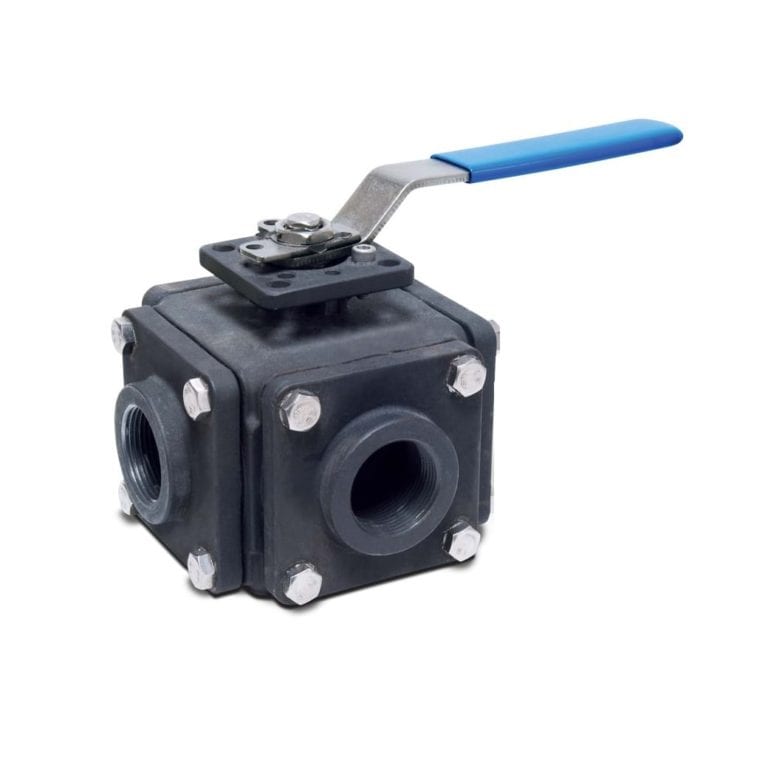
4-Way Valve (Non-Lubricated)
View More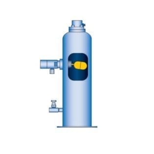
Automatic Liquid Trap
View More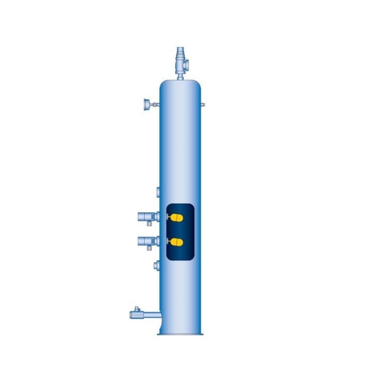
Automatic Liquid Trap (ASME Code-Stamped)
View More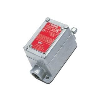
Low-Oil-Pressure Switch
View More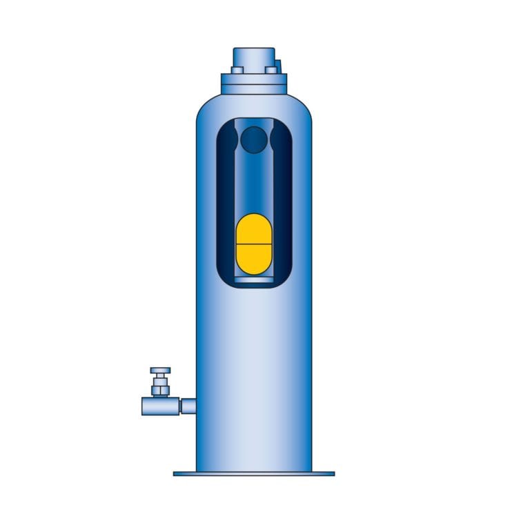
Mechanical Liquid Trap
View More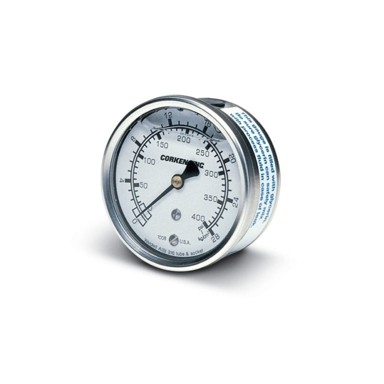
Pressure Gauges
View More
Strainer
View More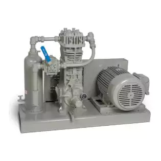
Corken 91 / F91 Compressor
View More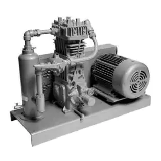
Corken 291 / F291 Compressor
View More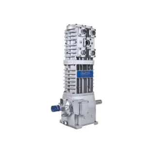
Corken 691 Compressor
View More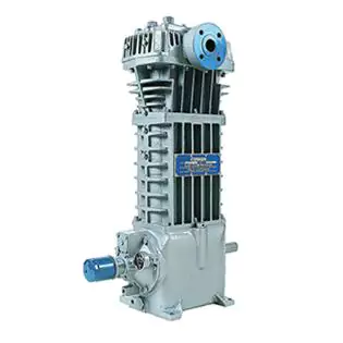
Corken FD891 Compressor
View More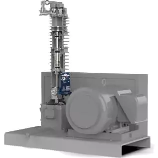
Corken UL Certified Plant Oil Extraction Compressor System
View More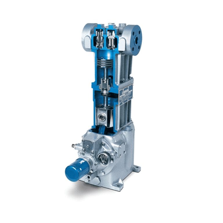
LPG Reciprocating Compressor
View More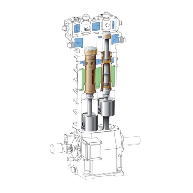
D-Style Oil-Free Reciprocating Compressors
View More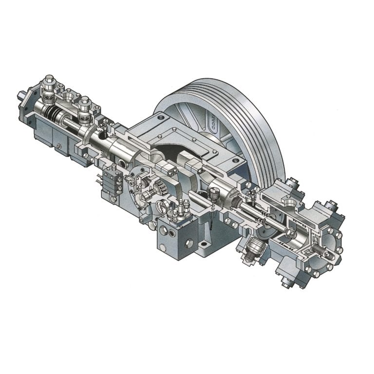
Single Packed Reciprocating Compressors (Non Oil Free)
View More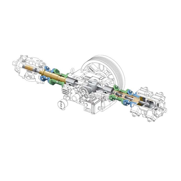
Triple Packed Reciprocating Compressors (Oil Free)
View More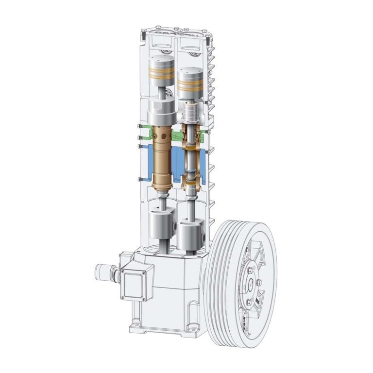
T-Style Oil-Free Reciprocating Compressors
View More